ELE-7
TP421
CF OUT
(GS)
TP422
TP422
Expand this portion.
B
Tori
er
CF OUT
(GS)
Tori
er
Tori
er
TP420
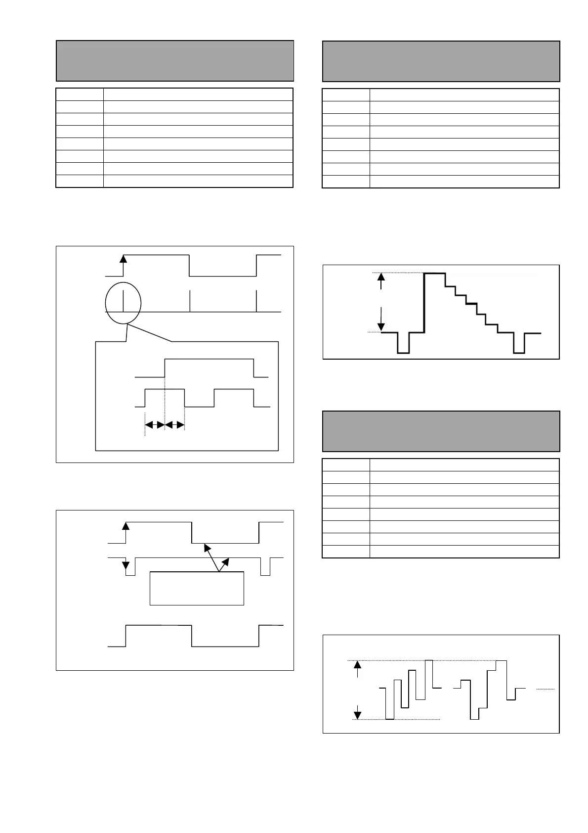
4-1a. Reference CF Detection
Adjustment (NTSC)
BOARD AVIO (F4)
TP
TP421, TP422
ADJ.
VR300
INPUT
SDI INPUT : 100% Color Bar
MODE
EE
TAPE
-----
M. EQ
Oscilloscope
SPEC.
A=B ± 5%
<Setup Menu>
070 --------- TV SYSTEM 525
1. Expand the pulse portion of TP422.
2. Adjust VR300 so that the widths A and B are
equal as shown below.
3. Make sure that the phase between the CF pulse
from the signal generator and TP420 is as shown
below.
4-2a. Component Y Level
Adjustment (NTSC)
BOARD AVIO (F4)
TP
Y OUT
ADJ.
VR202
INPUT
SDI INPUT : 100% Color Bar
MODE
EE
TAPE
-----
M. EQ
WFM
SPEC.
Video (V) = 714mV±3mV
<Setup Menu>
070 --------- TV SYSTEM 525
1. Press the Video Select button on the front panel
to select the Y/PB/PR mode.
2. Adjust VR202 so that the video level (V) is in the
specification.
4-3a. Component Y Level
Adjustment (NTSC)
BOARD AVIO (F4)
TP
PB/PR OUT
ADJ.
VR201 (PB), VR200 (PR)
INPUT
SDI INPUT : 100% Color Bar
MODE
EE
TAPE
-----
M. EQ
WFM
SPEC.
PR /PR = 1009mV±3mV
<Setup Menu>
070 --------- TV SYSTEM 525
1. Press the Video Select button on the front panel
to select the Y/PB/PR mode.
2. Adjust VR201 and VR200 so that the PB and PR
levels are in the specification.
Waveforms diffe
depending on
Y OUT
Video Level (V)
PB OUT
PB/PR
Level
PR OUT