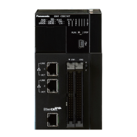
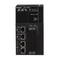
Output terminals (Line driver output type)
Pin No.
Circuit Signal name
Output specifications
Axis
1 / 3
Axis
2 / 4
Item Description
A1 A10
Pulse output A:
Line driver (+)
Output type
Line driver output
Equivalent to
AM26C31
B1 B10
Pulse output A:
Line driver (-)
A2 A11
Pulse output B:
Line driver (+)
B2 B11
Pulse output B:
Line driver (-)
Output terminals (common)
Pin No.
Circuit Signal name
Output specifications
Axis
1 / 3
Axis
2 / 4
Item Description
B5 B14
Servo ON output (+) Output type Open collector
Operating voltage
range
4.75 to 26.4 V DC
A7 A16
Deviation counter clear
(+)
Max. load current 10 mA
B7 B16
COM ON state max.
voltage drop
1.0 V
(Note 1) The deviation counter clear signal is output when the power supply is turned ON for about 1 ms. When
the home return is complete, the signal is output for about 1 ms or 10 ms. The time can be specified
using the "Parameter".
Power supply terminal (common)
Pin No.
Circuit Signal name
Power supply specifications
Item Description
A20
External power supply
input:
24 V DC (+)
Supplied power
supply range
21.4 to 26.4 V DC
B20
External power supply
input:
24 V DC (-)
Consumption current 90 mA or less
(Note 1) The external power supply input terminals between two connectors are connected internally.
3.3 Input / Output Specifications and Terminal Circuit Diagrams
3-8 WUME-GM1PG-01

 Loading...


