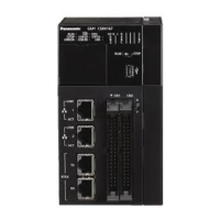
2.3 Names and Functions of Parts of the GM1 Pulse Output Unit
No. Name Function
(1) Unit connector This is a connector to which each expansion unit is connected.
(2) Operation monitor LEDs These LEDs indicate the status of expansion units.
(3)
Operation monitor selection
switch
This switches operation display between the display for axes 1 and
2, and that for axes 3 and 4.
(4) Output connector This is used to connect an output device.
(5) Expansion hook This is a hook used to fix each expansion unit to another.
(6) DIN rail attachment part This is the part which is attached to the DIN rail.
(7) DIN hook Used to fix the Controller to a DIN rail
■
Names and functions of each operation monitor LED
No. Name LED color Function
(1) Power Blue
Indicates the completion of power processing of the unit.
Lit: Power supply of the unit is started normally.
Unlit: Power is not supplied. Or, there is an error in the power supply
to the system.
(2) Alarm Red
Indicates that an alarm has occurred in the unit.
Lit: Unit error
Unlit: Normal
(3) A Green
Indicates the pulse output A signal.
(Note 1)
2.3 Names and Functions of Parts of the GM1 Pulse Output Unit
2-6 WUME-GM1PG-01

 Loading...