No. Name LED color Function
● When set to pulse / sign output method
Flashing: During pulse output
Unlit: During stop
● When set to CW / CCW output method
Flashing: During pulse output (Forward)
Unlit: During stop (Forward)
(4) B Green
Indicates the pulse output B signal.
(Note 1)
● When set to pulse / sign output method
Lit: Reverse direction command
Unlit: Forward direction command
● When set to CW / CCW output method
Flashing: During pulse output (Reverse)
Unlit: During stop (Reverse)
(5)
CL Green
Indicates the counter clear signal output.
Lit: Output ON
Unlit: Output OFF
(6) D Green
Indicates the near home status.
(Note 2)
Lit: ON
Unlit: OFF
(7) Z Green
Indicates the home input state.
(Note 2)
Lit: ON
Unlit: OFF
(8) PA Green
Indicates the pulse input A signal.
(Note 3)
(9) PB Green
Indicates the pulse input B signal.
(Note 3)
(10) ERR Red
Indicates that an error has occurred in the unit.
Lit: Error occurred.
Unlit: Normal
(Note 1) The pulse output signal display LEDs (A and B) blink at the output frequency (speed). For this reason
they may appear to light steadily at high-speed output.
(Note 2) The near home (D) and home input (Z) LEDs light when the respective input becomes valid.
(Note 3) Pulse input signal (PA) and (PB) display the pulse signal input status.
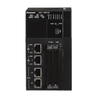
2.3 Names and Functions of Parts of the GM1 Pulse Output Unit
WUME-GM1PG-01 2-7

 Loading...