Parker Hannifin
P Series User Guide 61
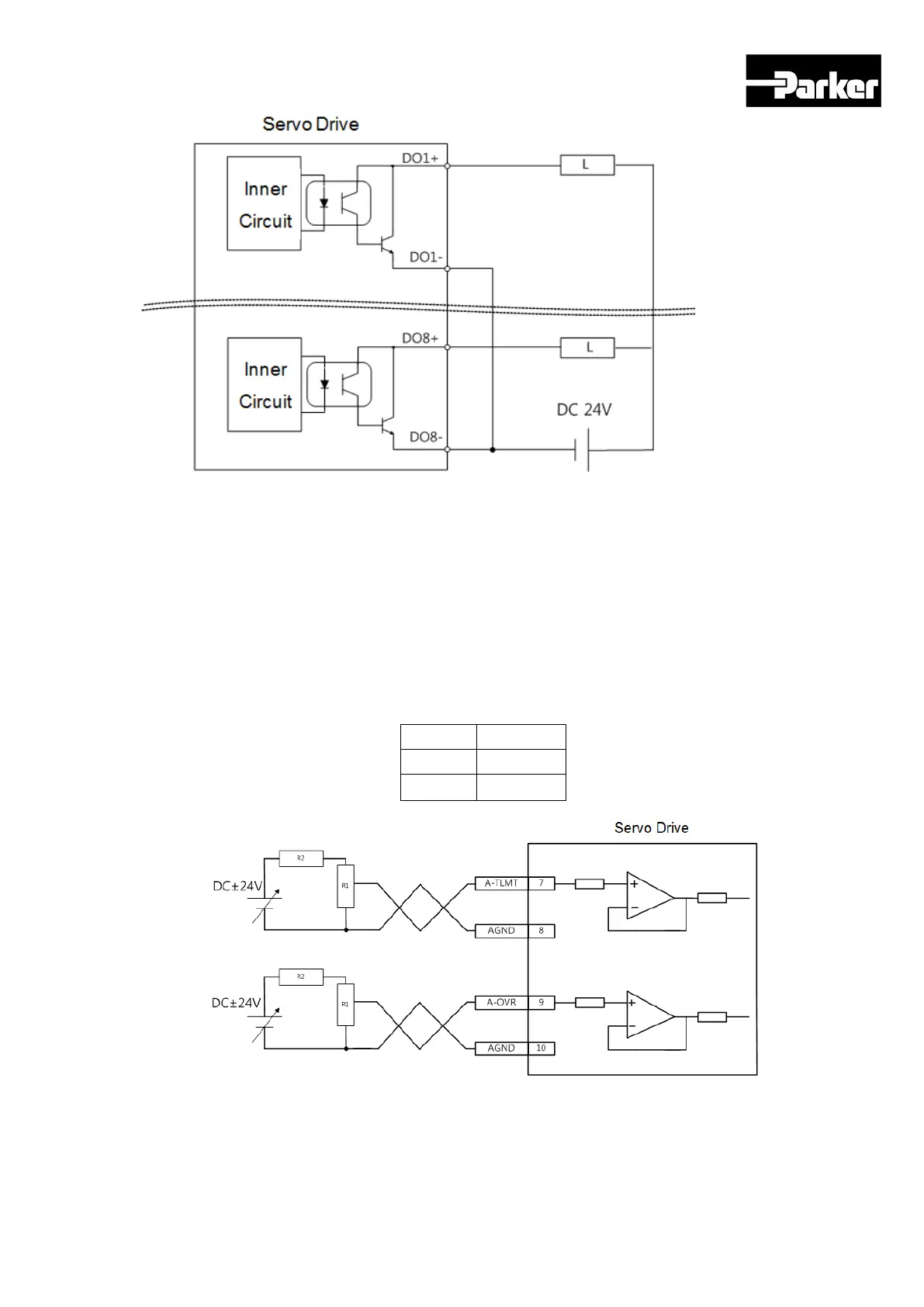
Figure 21. Example of Digital Output Signal Wiring
Note) For output signals DO1~ DO8, GND24 terminal is disconnected GND24.
Example of Analog Input Signal Wiring
Please see “ 8.5 Analog Speed Override “ and “ 6.10.3 Torque Limit Setting “ for operation
of analog input signals.
The window if analog input signal is -10V ~ 10V.
Impedance of the input signals is approximately 22KΩ.
Example of resistance selection
R1 R2
5KΩ 6KΩ
10KΩ 12KΩ
Figure 22. Example of Analog Input Signal Wiring

 Loading...


