Parker Hannifin
P Series User Guide 69
CRC
Input 16bit CRC value. The values are divided into MSB/LSB, and transmitted one byte at
a time.
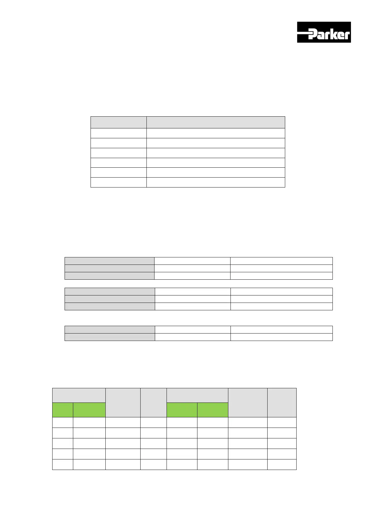
Exception Code
Exception codes for all function code abnormal responses supported by PD Drive are
defined as follows.
Exception Code Description
0x01 Function Code not supported
0x02 Wrong register address
0x03 Wrong data value
0x04 Device malfunction
0x05 Data not ready
0x06 Parameter locked
Table 25. Exception Code Description
4.2.4 Protocol Command Code Description
A. Read Coils (0x01)
Read the values of single bit and continuous bit block.
Request
Request OK
*N = Quantity of Outputs/8
Response not OK
Command code : Read Coils can read status of contacts of drive status input and
output1,2.
The corresponding address of drive status input and output 1,2 are as below.
Drive status input 1, 2 communication address
Output
contacts
Acces
sibility
Output
contacts
Access
ibility
Hexa decimal Hexa
0 0x0000
POT
RW 16 0x0016
START
RW
1 0x0001
NOT
RW 17 0x0017
PAUSE
RW
2 0x0002
RW 18 0x0018
RW
3 0x0003
STOP
RW 19 0x0019
HSTART
RW
4 0x0004
PCON
RW 20 0x0020
ISEL0
RW

 Loading...


