Parker Hannifin
P Series User Guide 51
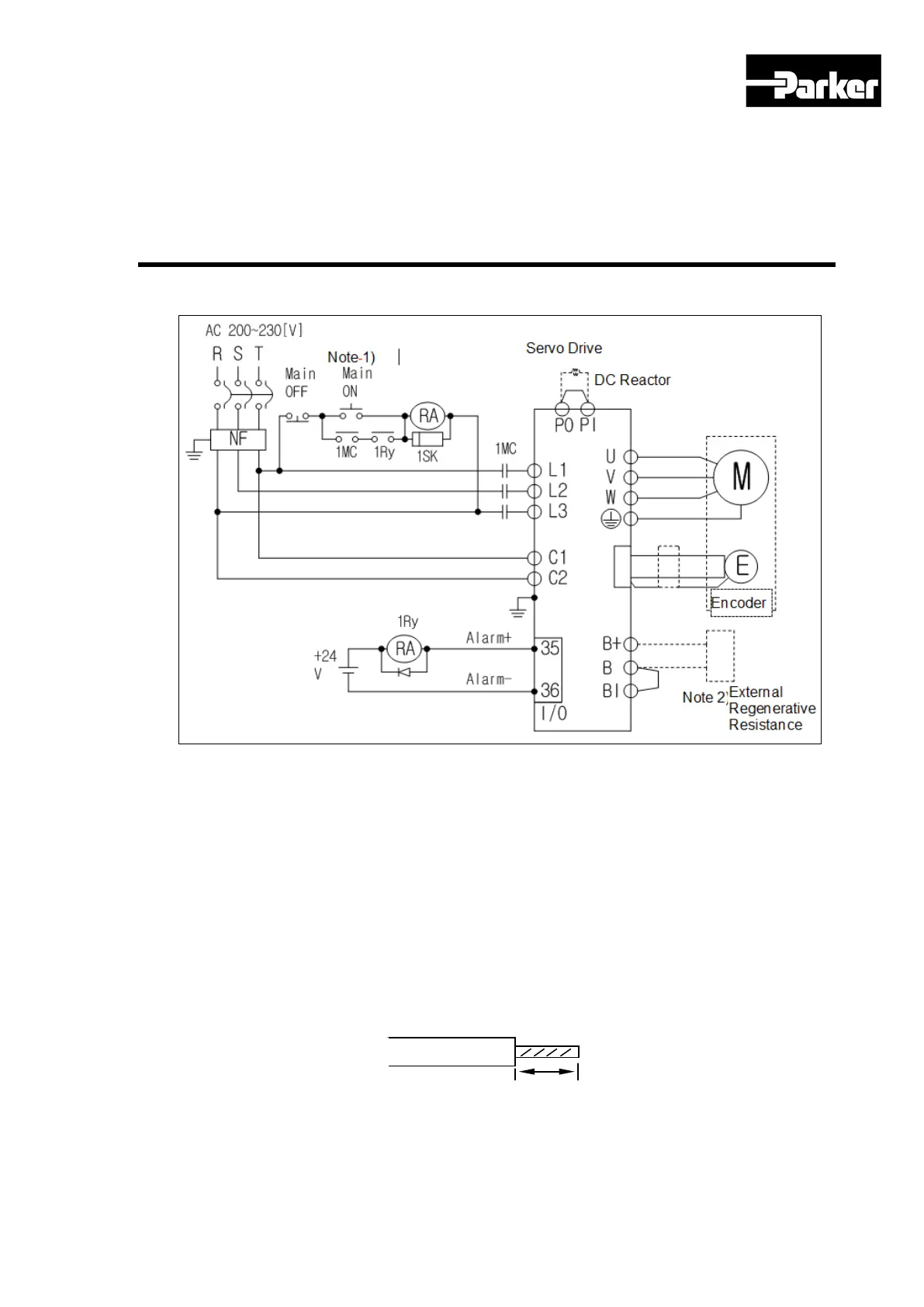
3.11.1 Power
Figure 18. Drive Wiring Example
Note 1) Please press the ON switch for the main power for at least 2 seconds, as the alarm
signal input takes 1~2 seconds after the main power is turned on.
Note 2) 400[W]drive has built-in recovery resistance of 50[W], 100[Ω], 1[kW]drive has
100[W], 40[Ω]; and 3.5[kW]drive has 150[W], 13[Ω] recovery resistance. Please
use them by shorting terminals B and BI. If the recovery resistance is high due to
frequent acceleration/deceleration, please open the shorting pins (B, BI) and
connect external recovery resistance to B, B+.
Note 3) Please peel off the 7~10[mm] of the sheath of the power cable to be used for the
power unit as shown in the figure below. And use the dedicated pressure terminal
(see “ 3.3.1 Power Circuit Electronics Specifications ”)
Note 4) When removing power unit wiring from 100[W]~1[kW] drive, remove or connect it
after pressing the button at the drive’s terminal block. In case of 2[kW]~3.5[kW]
drive, remove or connect it using a flat-head driver.
 Loading...


