Parker Hannifin
P Series User Guide 128
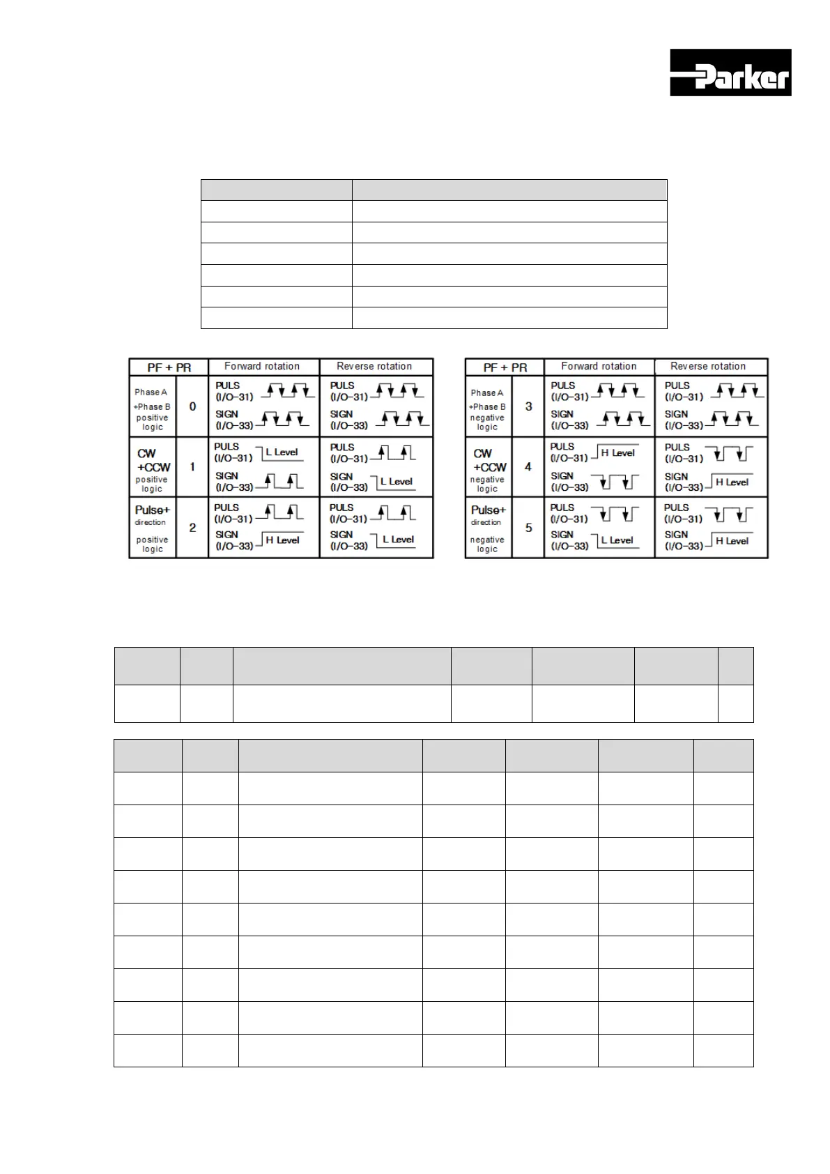
6.1.1 Function Setting of Pulse Input Logic
You can set the logic of the pulse strings from the host controller. The shapes of
the input pulses and the direction of rotation for each logic are as follows.
0 PHASE A + PHASE B, Positive Logic
1 CW + CCW, Positive Logic
2 Pulse + Sign, Positive Logic
PHASE A+PHASE B, Negative Logic
4 CW + CCW, Negative Logic
5 Pulse + Sign, Negative Logic
6.1.2 Related Objects
Index
Sub
Name
Variable
Accessibility
PDO
Unit
0x3003 - Pulse Input Logic Select UINT RW No -
Index
Name
Accessibility
Unit
0x6041 - Status word UINT RO Yes -
0x6062 - Position Demand Value DINT RO Yes UU
0x60FC -
Value
DINT RO Yes pulse
0x6063 -
Position Actual Internal
Value
DINT RO Yes pulse
0x6064 - Position Actual Value DINT RO Yes UU
0x60B1 - Speed Offset DINT RW Yes UU/s
0x60B2 - Torque Offset INT RW Yes 0.1%
0x606C - Speed Actual Value DINT RO Yes UU/s
0x6077 - Torque Actual Value INT RO Yes 0.1%
 Loading...


