EasyManuals Logo

Parker P Series User Manual

Parker P Series
316 pages
To Next Page IconTo Next Page
To Previous Page IconTo Previous Page
Page #123 background imageLoading...
Page #123 background image
Parker Hannifin
P Series User Guide 121
13
drive temperature2
°C
14
encoder temperature (Reserved)
°C
15
Hall sensor signal
16
phase U current
A
17
phase V current
A
18
phase W current
A
19
position actual value
UU
20
position demand value
UU
21
Position command speed
rpm
Table 68. Analog Monitor Channel Setting
The voltage for analog monitor output is calculated using the following formulas.
Channel 1 output voltage [V] = [monitoring signal value (0x2221) –offset (0x2203)] /
scale (0x2205)
Channel 2 output voltage [V] = [monitoring signal value (0x2222) –offset (0x2204)] /
scale (0x2206)
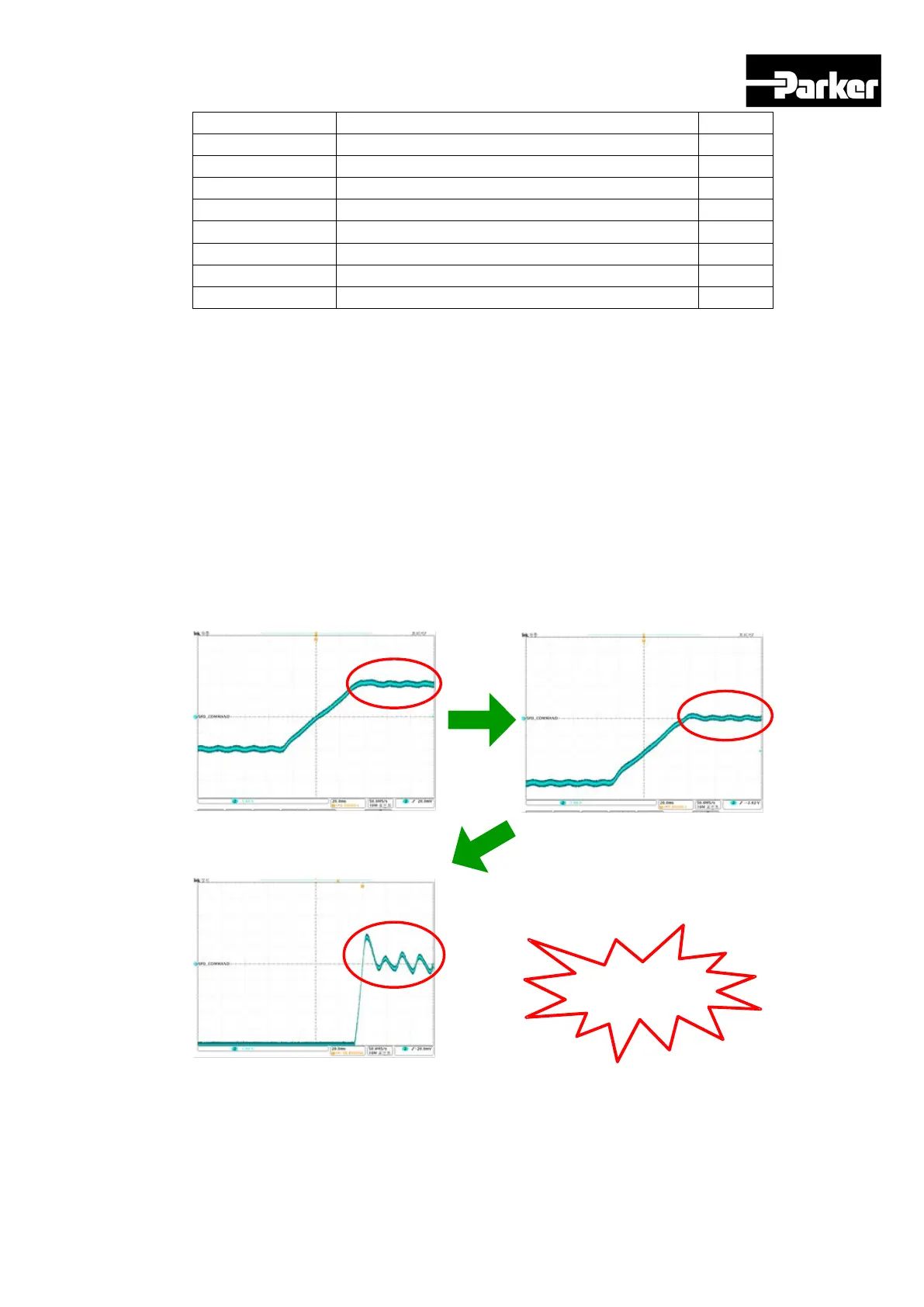
5.9.4 Setting Example
The figure below shows an example of monitoring when driving with speed feedback
signal of 1000rpm.
Monitors signals by
amplifying them 5
times
Output offset : 1000 rpm
Output scale : 500rpm/V
Output offset : 0 rpm
Output scale : 500rpm/V
Output offset : 1000 rpm
Output scale : 100rpm/V
Figure 38. Setting Example
www.comoso.com

Table of Contents

Questions and Answers:

Question and Answer IconNeed help?

Do you have a question about the Parker P Series and is the answer not in the manual?

Parker P Series Specifications

General IconGeneral
BrandParker
ModelP Series
CategoryServo Drives
LanguageEnglish

Related product manuals