Parker Hannifin
P Series User Guide 136
The purpose of torque control is to control such as tension or pressure of machine part by
voltage desired torque from upper controller.
Select ‘3’ in the control mode[0x3000]
For command torque, Enter analog -10[V] ~ +10[V] voltage to no.7 and no.8 on I/O
connector.
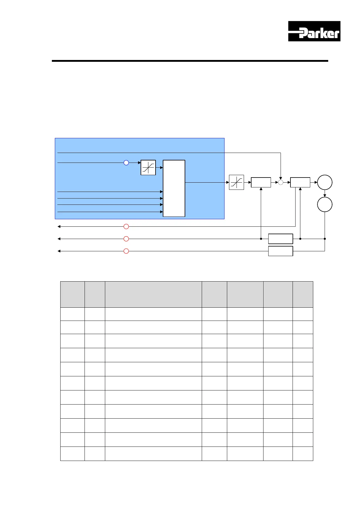
The Block diagram of velocity control mode is as below.
Torque Offset (
0x60B2)
Torque Actual Value
(0x6077)
Velocity Actual Value (0x606C)
Position Actual Value (0x6064)
Generate
Torque
Command
Velocity
Control
Torque
Control
+
+
M
Enc.
Velocity
Calculation
Position
Calculation
OP Mode : Torque
6
7
8
1
Analog Torque Command(A-TLMT)
Speed Limit Value at Torque control Mode(0x230E)
Analog Torque Command Filter Time Constant(0x2228)
Analog Torque Input(command/limit) Offset(0x221D)
Analog Torque Input(command/limit) Scale(0x221C)
Index
Index
Name
Format
Accessibility
Allocation
Unit
0x6062 - Position Demand Value DINT RO Yes UU
Position Demand Internal Value
Position Actual Internal Value
0x60B1 - Velocity Offset DINT RW Yes UU/s
0x606C - Velocity Actual Value DINT RO Yes UU/s
 Loading...


