Parker Hannifin
P Series User Guide 91
** LVSF2
Vibration
Suppression
Filter 2
Vibration control filter signal 2 according
to setting function (0x2515) for Vibration
control filter.
This is the same as predetermined value
of SPD2 when allocating.
Table 48. Digital Input Signal Description
Note ) **These signals are not allotted at the time of the product’s release from the
factory. You can change allotment by configuring the parameters. Please see “ 4.5 I/O
Signal Setting “ for further details.
Note ) You may perform wiring by using the COMMON (DC 24V) of the input signal as
GND.
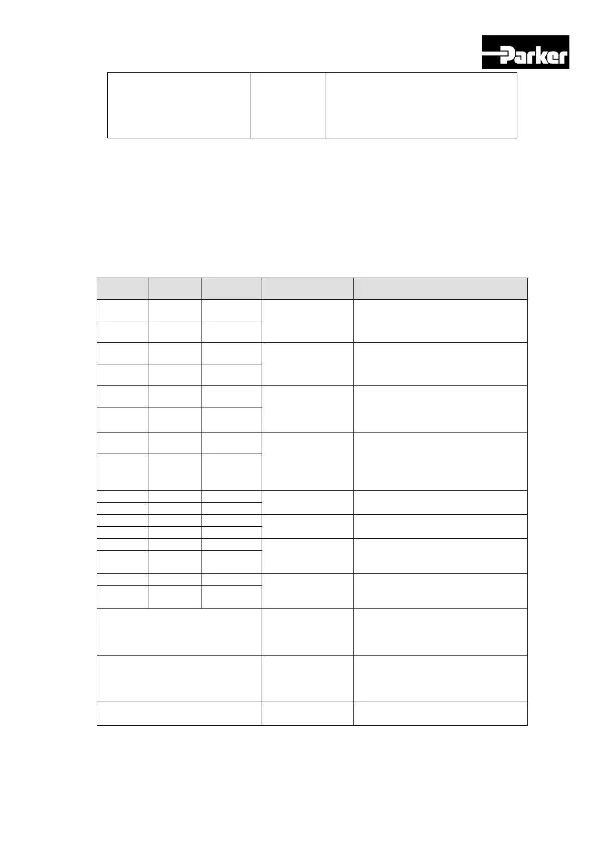
Digital Output Signals (I/O Connector)
Pin No. Name Allotment Description Function Details
35 DO1+ ALARM+
Servo alarm
This signal is displayed when the
servo alarm sets off.
36 DO1- ALARM-
37 DO2+ RDY+
Servo ready
This signal is displayed when the
main power is on and the servo is
operational.
38 DO2- RDY-
39 DO3+ BRAKE+
Brake
This signal is for controlling brakes
installed inside or outside the motor.
It is displayed when the SVON
40 DO3- BRAKE-
41 DO4+ INPOS1+
Position reached
1
This signal is displayed when the
command position is reached. You
can set the display conditions by
adjusting the [0x2401], [0x2402]
42 DO4- INPOS1-
Original position
reached
This signal is displayed when origin
operation is complete.
This signal is displayed when index
operation is complete.
Rotation detection
This signal is displayed when the
motor rotates faster than the set
48 DO7- TGON-
Torque limit
This signal is displayed when the
drive output is limited within the set
50 DO8- TLMT-
** VLMT Speed limit
This signal is displayed when the
motor reaches the speed limit. The
speed limit can be adjusted by setting
the [0x230D], [0x230E] values.
** INSPD Speed reached
This signal is displayed when the
difference between the command
speed and the current speed is under
** WARN Servo warning
This signal is displayed when a
warning sets off.
 Loading...


