Workshop Manual, TSD3450E, Issue 1 103
11
2800
Fuel system 11
General information
The fuel supply circuit used on the 2806 engine is a conventional design for engines fitted with unit injectors.
A fuel transfer pump, driven by the timing gears of the engine, is fitted behind the gear case on the left side of
the engine. The fuel transfer pump draws fuel from the fuel tank. The fuel is filtered by the primary fuel filter
before it enters the transfer pump. From the transfer pump, the fuel is filtered by the secondary fuel filter and
is then supplied to the fuel gallery in the cylinder head. The fuel injectors draw fuel from the gallery and return
the spill fuel to the same gallery. A pressure relief valve ensures that the pressure in the gallery is maintained
and any excess fuel is returned to the fuel tank.
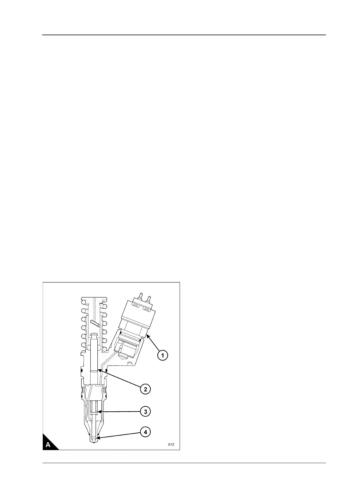
Each unit injector is operated, through a rocker lever, by a lobe of the camshaft. This provides the force
required to pressurize the fuel in the injector. The camshaft has three lobes for each cylinder, the other two
lobes operate the inlet and exhaust valves. The unit injectors are fitted with a solenoid (A1) which is
electronically controlled by the ECM (engine control module).
Low pressure fuel circulates through the body of the unit injector and excess fuel is returned to the fuel gallery
through a spill port. When the solenoid of the unit injector is activated by a signal from the ECM, it closes the
escape route for the fuel and the pressure increases in the injector tip (A4).
Injection begins when the pressure in the tip reaches 34464 kPa (5,000 lb/in
2
). At this pressure the force
applied by the spring (A3) is not sufficient to keep the nozzle closed. As the plunger (A2) moves through its full
stroke, the pressure increases. When the correct amount of fuel has been injected, the ECM de-energises the
solenoid. This opens the spill port and the reduction in pressure allows the spring (A3) to close the injector
nozzle. The high-pressure fuel which passes through the spill port returns to the fuel gallery.
During maintenance of the fuel system, clean thoroughly each component before it is removed or dismantled
and fit suitable caps and plugs to all unions immediately after they have been disconnected.
Operations for the unit injectors and the injector sleeves are given in Chapter 3 Cylinder head assembly.