2
Workshop Manual, TSD3450E, Issue 1 23
2800
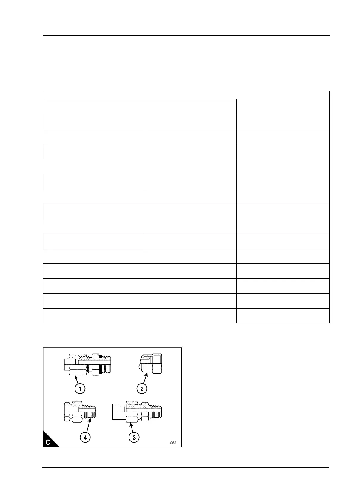
Torque figures for flared and ‘O’ ring fittings
The torque figures given in the table below and the table given on page 17 should be applied to the nut of the
fittings which follow: 37 degree flared fittings (C1), 45 degree flared fittings (C3), inverted flared fittings (C2),
‘O’ ring fittings for a recessed drive, ‘O’ ring fittings for air conditioning and swivel nuts (C2). The figures should
be used for applications which allow these working pressures: 7750 to 34450 kPa (1125 to 5000 lb/in²). The
torque figure depends on the size and type of fitting.
Note: For the table above, use 50 percent of the torque figure when the fitting, the plug or the port material is
nonferrous.
Nuts for 37 degree flared fittings
Outside diameter of nominal tube
Thread size
Inches
Standard
torque
3,18 mm
(0.125 in)
5/16
5,0 +/- 1,5 Nm
(4 +/- 1 lbf ft)
4,76 mm
(0.188 in)
3/8
11 +/- 2 Nm
(8 +/- 1 lbf ft)
6,35 mm
(0.250 in)
7/16
16 +/- 4 Nm
(12 +/- 3 lbf ft)
7,94 mm
(0.312 in)
1/2
20 +/- 5 Nm
(15 +/- 4 lbf ft)
9,52 mm
(0.375 in)
9/16
25 +/- 5 Nm
(18 +/- 4 lbf ft)
9,52 mm
(0.375 in)
5/8
35 +/- 5 Nm
(26 +/- 4 lbf ft)
12,70 mm
(0.500 in)
3/4
50 +/- 7 Nm
(37 +/- 5 lbf ft)
15,88 mm
(0.625 in)
7/8
65 +/- 7 Nm
(48 +/- 5 lbf ft)
19,05 mm
(0.750 in)
1 1/16
100 +/- 10 Nm
(75 +/- 7 lbf ft)
22,22 mm
(0.875 in)
1 3/16
120 +/- 10 Nm
(90 +/- 7 lbf ft)
25,40 mm
(1.000 in)
1 5/16
135 +/- 15 Nm
(100 +/- 11 lbf ft)
31,75 mm
(1.250 in)
1 5/8
180 +/- 15 Nm
(135 +/- 11 lbf ft)
38,10 mm
(1.500 in)
1 7/8
225 +/- 15 Nm
(165 +/- 11 lbf ft)
50,80 mm
(2.000 in)
2 1/2
320 +/- 30 Nm
(240 +/- 22 lbf ft)