8
88 Workshop Manual, TSD3450E, Issue 1
2800
Electronic control module
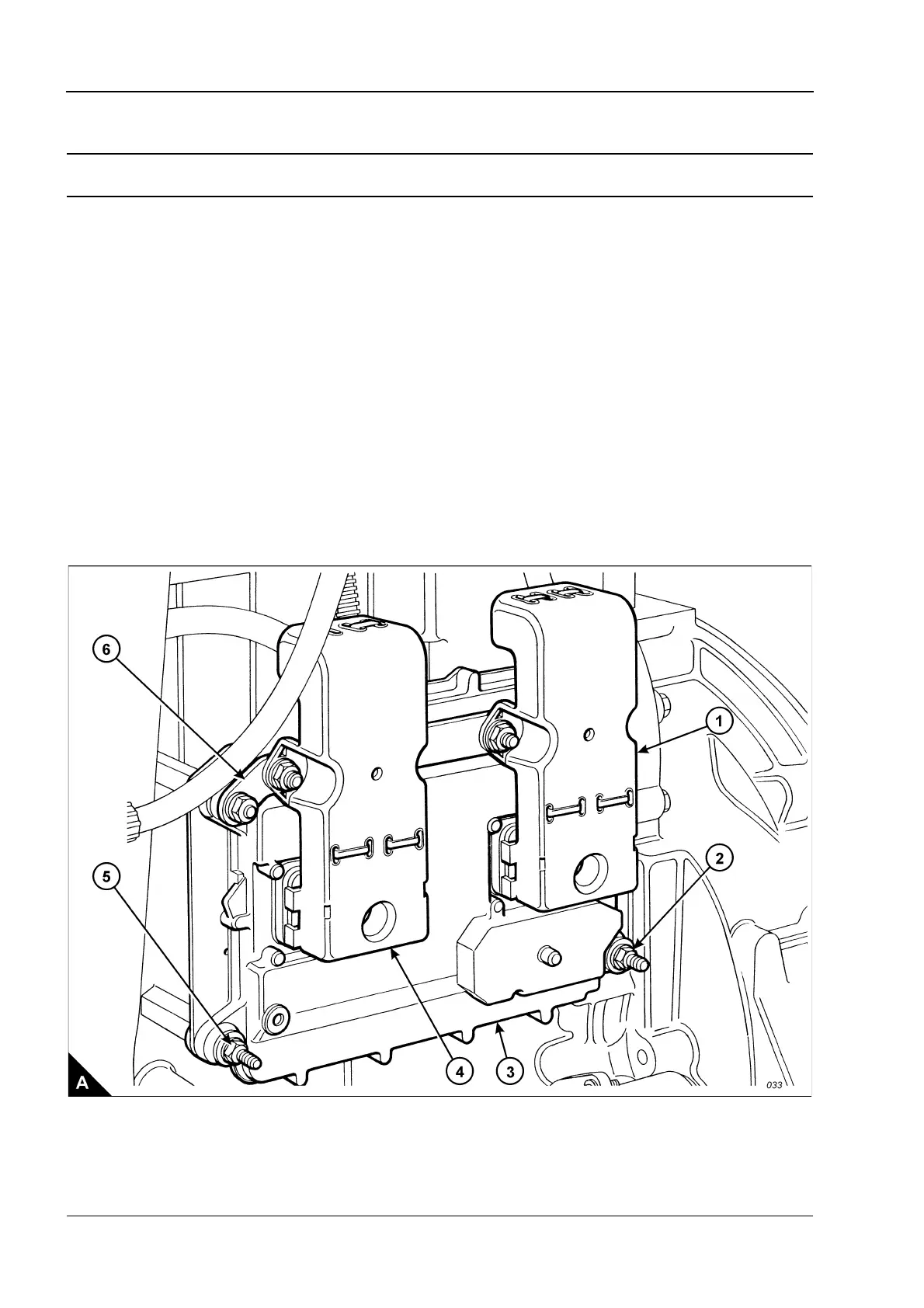
To remove and to fit Operation 8-1
To remove
1 Switch off the engine and disconnect the electrical power supply.
2 Loosen fully the Allen screws from the J1 and J2 connectors (A1 and A4).
3 Remove the two nuts which retain the bar (A6) and the control module (A3), release the ground strap and
withdraw the bar and connectors from the control module.
4 Support the control module, remove the two remaining nuts (A2 and A5) and remove the electronic control
module from the engine.
To fit
1 Fit the electronic control module. Retain with four nuts, ensure that the ground strap is fitted correctly.
Note: To avoid damage to the components, use the Allen screws to pull the mating parts of the connectors
(A1 and A4) and control module (A3) together. Ensure that the connectors are aligned correctly and are fitted
to the correct positions before the Allen screws are tightened.
2 Fit the connectors (A1 and A4) and retain with Allen screws. Tighten the screws to a torque of 6 +/- 1 Nm
(53 +/- 9 lb in). Do NOT overtighten the screws.
3 Connect the electrical power supply.