2
Workshop Manual, TSD3450E, Issue 1 15
2800
Crankcase and cylinder liners
Thickness of spacer plate (H3) ... ... ... ... ... ... ... ... ... ... ... ... ... ... 8,585 +/- 0,025 mm (0.3380 +/- 0.0010 in)
Thickness of gasket fitted between spacer plate and crankcase ... 0,238 +/- 0,032 mm (0.0094 +/- 0.0013 in)
Cylinder liner protrusion (H5) above the spacer plate . ... ... ... ... ... ..0,025 to 0,152 mm (0.0010 to 0.0060 in)
Maximum variation in each cylinder liner. ... ... ... ... ... ... ... ... ... ... ... ... ... ... ... ... ... ... 0,051 mm (0.0020 in)
Maximum average variation between adjacent cylinder liners ... ... ... ... ... ... ... ... ... ... 0,051 mm (0.0020 in)
Maximum variation between all cylinder liners ... ... ... ... ... ... ... ... ... ... ... ... ... ... ... ... 0,102 mm (0.0040 in)
Refer to Operation 7-3 for further cylinder liner information.
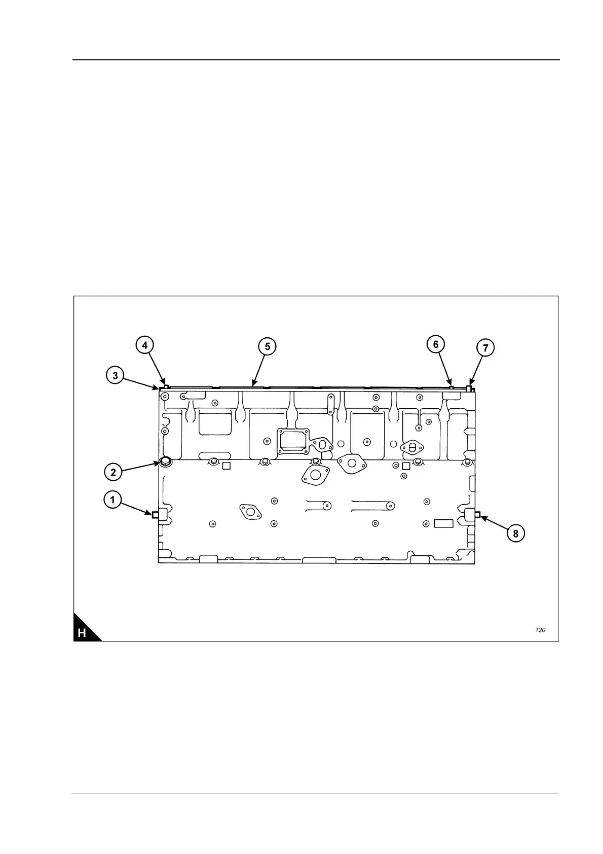
Protrusion of front cylinder head dowel (H6) above top face of crankcase . . 16,0 +/- 0,5 mm (0.63 +/- 0.02 in)
Protrusion of rear cylinder head dowel (H4) above top face of crankcase.. . 18,5 +/- 0,5 mm (0.73 +/- 0.02 in)
Protrusion of oil transfer tube (H7) above top face of crankcase ... ... ... ... . 20,0 +/- 0,5 mm (0.79 +/- 0.02 in)
Protrusion of flywheel housing dowels (H1) from rear face of crankcase ... . 19,1 +/- 0,5 mm (0.75 +/- 0.02 in)
Protrusion of gear case dowels (H8) from front face of crankcase.. ... ... ... . 19,1 +/- 0,5 mm (0.75 +/- 0.02 in)
Plug (H2) must be tightened to a torque of.. ... ... ... ... ... ... ... ... ... ... ... ... ... ... ..70 +/- 10 Nm (52 +/- 7 lbf ft)
The total flatness of the top face of the crankcase must be within 0,10 mm (0.004 in). The flatness must also
be within 0,05 mm (0.002 in) for any 177,5 mm (6.99 in) section of the surface.
Continued