3
Workshop Manual, TSD3450E, Issue 1 29
2800
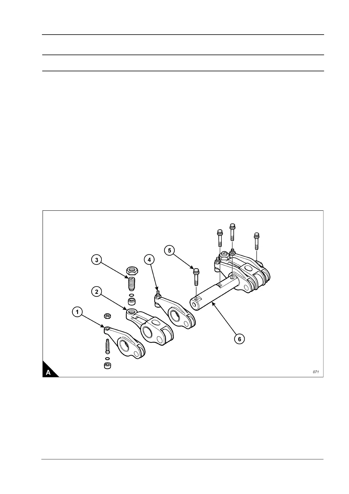
Rocker lever and rocker shaft assemblies
To remove and to fit Operation 3-2
To remove
1 Remove the rocker cover, Operation 3-1.
2 The valve rocker levers (A1) and the unit injector rocker levers (A2) can move on the shaft (A6) after the four
bolts (A5) have been removed. The shaft (A6) should be kept level when removed from the cylinder head. To
avoid possible personal injury, keep fingers clear of the rocker levers (A1 and A2) during removal of the
assembly from the cylinder head.
3 Remove the four bolts (A5).
4 Remove the shaft (A6), valve rocker levers (A1) and unit injector rocker levers (A2) as a unit.
5 Repeat steps 1 and 2 for the rocker shaft assemblies which remain.
To fit
1 Loosen the adjustment screws (A3 and A4) of each of the rocker levers which have been removed. Install
the rocker shaft assembly in the reverse order to removal.
2 Set the tappet clearances, Operation 3-4.
3 Check/adjust the unit injectors, Operation 3-13.
4 Fit the rocker cover, Operation 3-1.