3
32 Workshop Manual, TSD3450E, Issue 1
2800
How to check/adjust the tappet clearances Operation 3-4
Special requirements
The tappet clearance is measured between the rocker levers and the top of the valve bridge pieces. The
operation must be done with the engine cold and stopped. Refer also to Operation 3-13, How to check/adjust
the electronic unit injectors.
1 Remove the rocker cover, Operation 3-1.
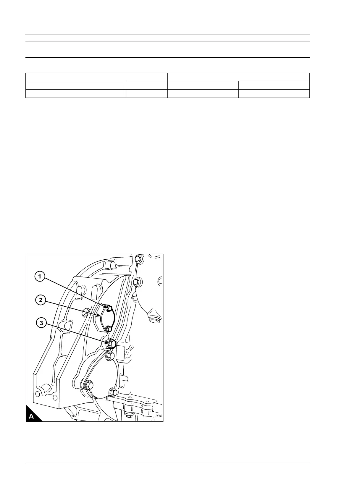
2 Remove the top bolt (A1) from the cover (A2) on the flywheel housing and loosen the other cover bolt to
allow the cover to open. The top bolt (A1) is the timing bolt.
Caution: If a customer-fitted speed sensor is fitted to the flywheel housing, it must be removed before the
engine turning tool can be inserted.
3 Remove the plug (A3) from the timing bolt location in the flywheel housing and fit the timing bolt.
Note: There are two locations for the timing bolt, one at each side of the flywheel housing. Use the location
that is the most convenient.
4 Insert the engine turning tool, CH11148, into the flywheel housing through the aperture behind the cover
(A2). Use a
1
/
2
inch drive ratchet with the turning tool to rotate the engine flywheel in the normal direction of
rotation (anti-clockwise when viewed on the flywheel) until the timing bolt engages with the threaded hole in
the flywheel. The piston of number 1 cylinder is now at TDC (top dead centre).
Caution: If the flywheel is turned past the threaded hole, the flywheel must be turned in the opposite direction
for approximately 45 degrees and then back in the normal direction of rotation until the timing bolt engages
with the threaded hole. This is to eliminate backlash.
Continued
Special tools Tappet clearances
Description Part number Inlet Exhaust
Engine turning tool CH11148 0,38 mm (0.015 in) 0,76 mm (0.030 in)