6
Workshop Manual, TSD3450E, Issue 1 75
2800
Timing gears
To remove and to fit Operation 6-2
Special requirements
To remove
1 Remove the gear case cover, Operation 6-1, and set the engine to the correct timing position for number
one cylinder as follows:
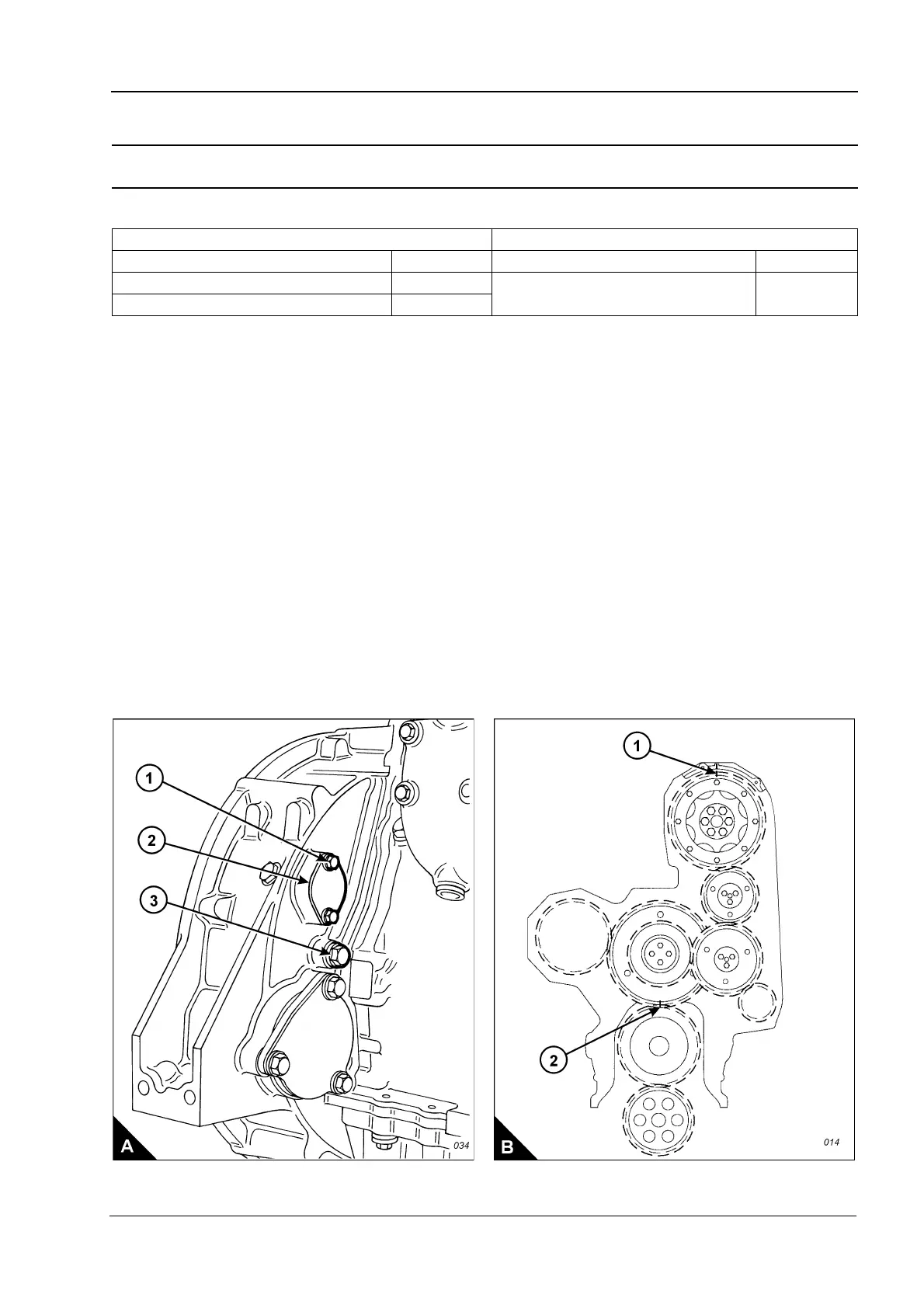
2 Remove the top bolt (A1) from the cover (A2) on the flywheel housing and loosen the other cover bolt to
allow the cover to open. The top bolt (A1) is the timing bolt.
Caution: If a customer-fitted speed sensor is fitted to the flywheel housing, it must be removed before the
engine turning tool can be inserted.
3 Remove the plug (A3) from the timing bolt location in the flywheel housing and fit the timing bolt.
4 Insert the engine turning tool, CH11148, into the flywheel housing through the aperture behind the cover
(A2). Use a
1
/
2
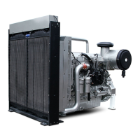
inch drive ratchet with the turning tool to rotate the engine flywheel in the normal direction of
rotation (anti-clockwise when viewed on the flywheel) until the timing bolt engages with the threaded hole in
the flywheel. When the number one piston is at top dead centre on its compression stroke, the mark on the
camshaft gear is be aligned with the mark on the gear case (B1). If the mark is not aligned, withdraw the timing
bolt, rotate the crankshaft a further 360 degrees in the normal direction of rotation and insert the timing bolt
again.
Caution: If the flywheel is turned past the threaded hole, the flywheel must be turned in the opposite direction
for approximately 45 degrees and then back in the normal direction of rotation until the timing bolt engages
with the threaded hole. This is to eliminate backlash.
Continued
Special tools Consumable products
Description Part number Description Part number
Engine turning tool CH11148
Thread lock compound (10 ml) 21820 117
Guide stud GE50019