3
Workshop Manual, TSD3450E, Issue 1 53
2800
To check and to adjust Operation 3-13
Special requirements
This operation should be performed at the same time as the operation to check the valve tappet clearances.
Warning! The electrical circuit for the fuel injector units operates on 110 volts. Do NOT work on the fuel injector
units unless the power supply to the ECM has been disconnected.
1 With the rocker covers removed, set the number 1 piston to TDC (top dead centre) on its compression
stroke. Check/adjust the height dimensions for the fuel injectors of cylinders 3, 5 and 6.
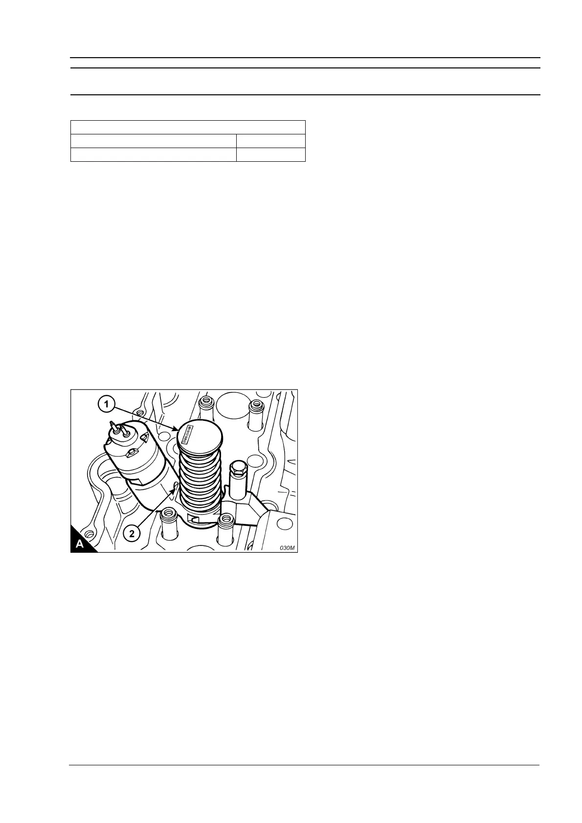
2 Use the fuel injector setting gauge, CH11149, to obtain the correct height for the fuel injector. The dimension
to be measured is from the top of the unit injector (A1) to the machined ledge on the fuel injector body (A2).
This dimension should be 78,0 +/- 0,2 mm (3.07 +/- 0.01 in). Slacken the lock nut and use the adjustment screw
of the rocker lever to obtain the correct dimension. Tighten the lock nut to a torque of 55 +/- 10 Nm (41 +/-
7lbfft).
3 Remove the timing bolt from the flywheel housing and rotate the flywheel by 360 degrees in the normal
direction of engine rotation until the timing bolt can be inserted into the threaded hole. This will put the number
1 piston at TDC in its exhaust stroke.
4 Check/adjust the height dimensions for the fuel injectors of cylinders 1, 2 and 4 as given in step 2.
When all adjustments have been made, remove the timing bolt, fit the cover to the flywheel housing, fit the plug
to the timing bolt position and fit the rocker covers.
Special tools
Description Part number
Injector height gauge CH11149