Functional Description of the Monitor Hardware
16
Introduction to the Instrument
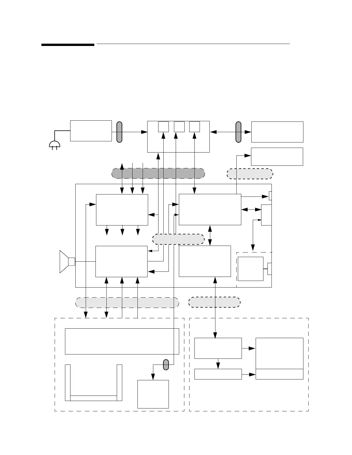
Functional Description of the Monitor Hardware
The Monitor receives data from the Measurement Server and Measurement Server Extension
via the Server-to-Monitor link bar and presents this data on the color LCD display. The
following block diagram shows the main functional areas.
AC
Power Supply
AC
Smart Battery
Optional
Vbat,
I2C
LAN
Connector
Bezel Assembly
Keyboard
TouchStrips
IrDA
Standby On/Off (PIC)
4 hardkeys(HIF)
LEDs:
X Bell(HIF)
red alarm(HIF)
yellow alarm(HIF)
On/Off(+5V)
AC Power(PIC)
Battery(PIC)
Display Adapter
Board
Inverter Board
LCD
Display
Backlight
48 Pin
DC/DC Converter
48V current limiter
Battery charger
Display
ECG
Out
SRL to
Measuremen
CPU System(360)
(Flash,SRAM,DRAM)
HIF(83C552)
(TouchStrip,Keys,Sound,
LEDs, Alarm Relay,
Battery)
34 Wire
40 Wire
Processor (Battery
6 Pin
2x2 Pin
31 Pin
Flat Cable
Flat Cable
cable
Flex
cable
Connector
6 Pin
Connector
5 Pin
Connector
48V,
AC present
(Network)
SRL
LAN
Serial Link
uP bus
Video
I2C
Rx,Tx
TouchStrip
Keys
Alarm LEDs
PIC LEDs,Standby
Vbat 48V
AC
present
I2C
Board
(Infrared)
Display Assembly
Video
Controller
Controller)
Server
Alarm
Relay
VGA
(M3000A)
48Vlim +5V Vbuf
ECG Out/
Marker In
Controller
System Board
Ventilator
Fan
Wireless LAN
Optional
Connector
140 Pin
or
Serial
Interface