MSL Cable Termination
112
Installin
the Instrument
MSL Cable Termination
The following installation procedure describes how to install the wall installation cable kit
when the patient monitor and the measurement server are not located at the same site. The kit
consists of two connector boxes and a cable (15m or 25m).
For this procedure you need the Insertion Tool (M3086-43801) and a small screwdriver.
Step 1 Draw the MSL cable through the wall from the site of the monitor to the site of the
measurement server.
Each MSL face plate kit contains two connector boxes; one in-going and one out-
going. (The US version contains an additional rectangular wall-mounting plate).
NOTE
The installation procedure is the same for both connector boxes. This means you must
perform steps 3 to 8 of this procedure twice.
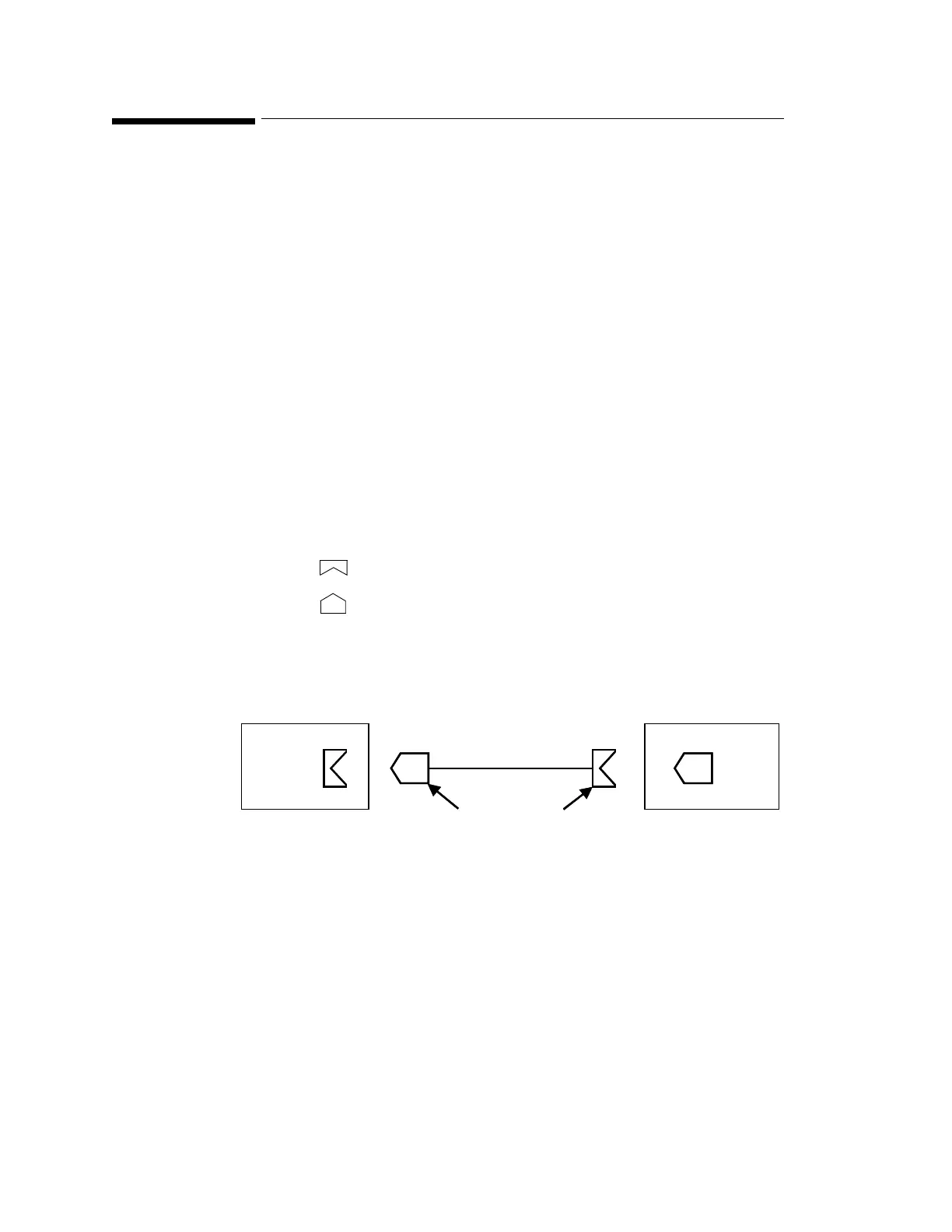
The connectors on each box are different, so you must ensure that the correct box is placed at
the correct location. The symbol on the plastic angled cover indicates at which site you
should install the box:
Symbol: is connector box (in) and must be placed at the monitor site.
Symbol: is connector box (out) and must be placed at the measurement server site.
The correct connector cable (M3081-61601, M3081-61602 or M3081-61603) has the
opposite symbol:
If there are no symbols on the cover, dots are used:
Step 2 Detach the PCB assembly (in/out) from the metallic mounting flange.
At Monitor Site At Measurement Server Site
Connector Box (in)
Cable
Symbols on Cable
Connector
Connector Box (out)
At Monitor Site At Measurement Server Site
Connector Box (in)
Cable
Symbols on Cable
Connector
Connector Box (out)
•• ⇔ •• and • ⇔ •