Arterial Oxygen Saturation and Pleth (SpO
2
/PLETH) Measurement
34
Introduction to the Instrument
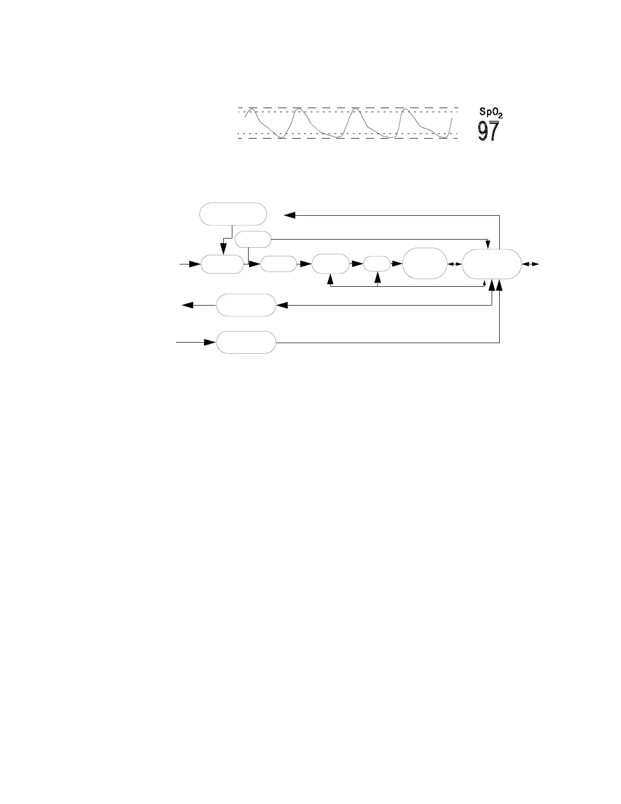
This illustration contains an example of a typical wave in SpO
2
.
Block Diagram of the SpO
2
/PLETH Circuit
Theory of Operation
The signals progress through the circuit as follows:
LED Current Source
This generates the LED current from a constant voltage provided by the power supply. A
bridge consisting of four transistors switches the LED current for driving the red and infrared
LEDs. These switching transistors are controlled by the SpO
2
CPU.
Photo Amplifier
The photo amplifier is an active input current to voltage converter. The input signal is filtered
by a low pass filter to eliminate higher frequencies generated, for example, by electro-surgery
units. Then the input current from the photo diode of the sensor is converted to a voltage.
Clipping Detector
A comparator detects clipping of the photo-amplifier signal caused by, for example, ambient
light. The clipping detection is connected directly to the SpO
2
CPU to generate an INOP if
necessary.
Pleth
To & From SpO2 Transducer
photo
LED
Rtype/
Rlambda
Self-Test Signal
Generator
Photo
Clipping
Detector
LED Current
Source
RCode
Measurement
Va ri ab l e
Gain
ADC
Digital
Signal
Processor
CPU
ROM/RAM
ASIC
current
current
To & From System CPU
Bandpass
Amplifier