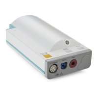
Functional Description of the M3016A Measurement Server Extension Hardware
Introduction to the Instrument
55
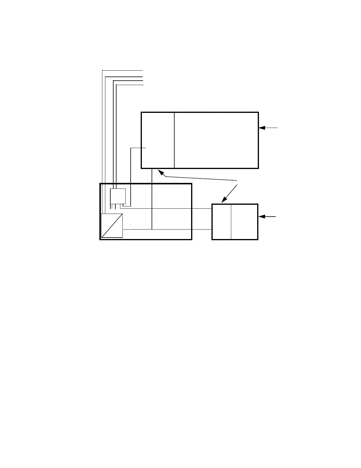
Hardware Block Diagram
Main Functional Areas
• Front-End Board - consisting of the CO
2
Front-End, PRESS/TEMP Front-End and the
Floating/Non-floating isolation area all feeding signals to the DC/DC Converter Board.
• DC/DC Converter Board - connecting to the Floating/Non-floating isolation area on the
Front-End Board. Consisting also of a multiplexer for Front-End Link communication to
the Measurement Server.
Power Supply
PRESS/
TEMP
Mainstream CO
2
MUX
36-60V
28Vpp
+/-2%
Isoblock
Optocoupler and
Power transformer
36 - 60 Volt
Power Sync
RxD/TxD
FEL Addresses
CO
2
Transduce
Pressure or
Temperature
Transducer
Opto-coupler
and Power
Transformer
SRL Connector
to Measurement Server
}
Floating/Non-floating
isolation
(MSL connector)