User Manual
E727T0005, valid for E-727
BRO, 2019-06-28
Physik Instrumente (PI) GmbH & Co. KG, Auf der Roemerstrasse 1, 76228 Karlsruhe, Germany Page 195 / 240
Phone +49 721 4846-0, Fax +49 721 4846-1019, Email info@pi.ws, www.pi.ws
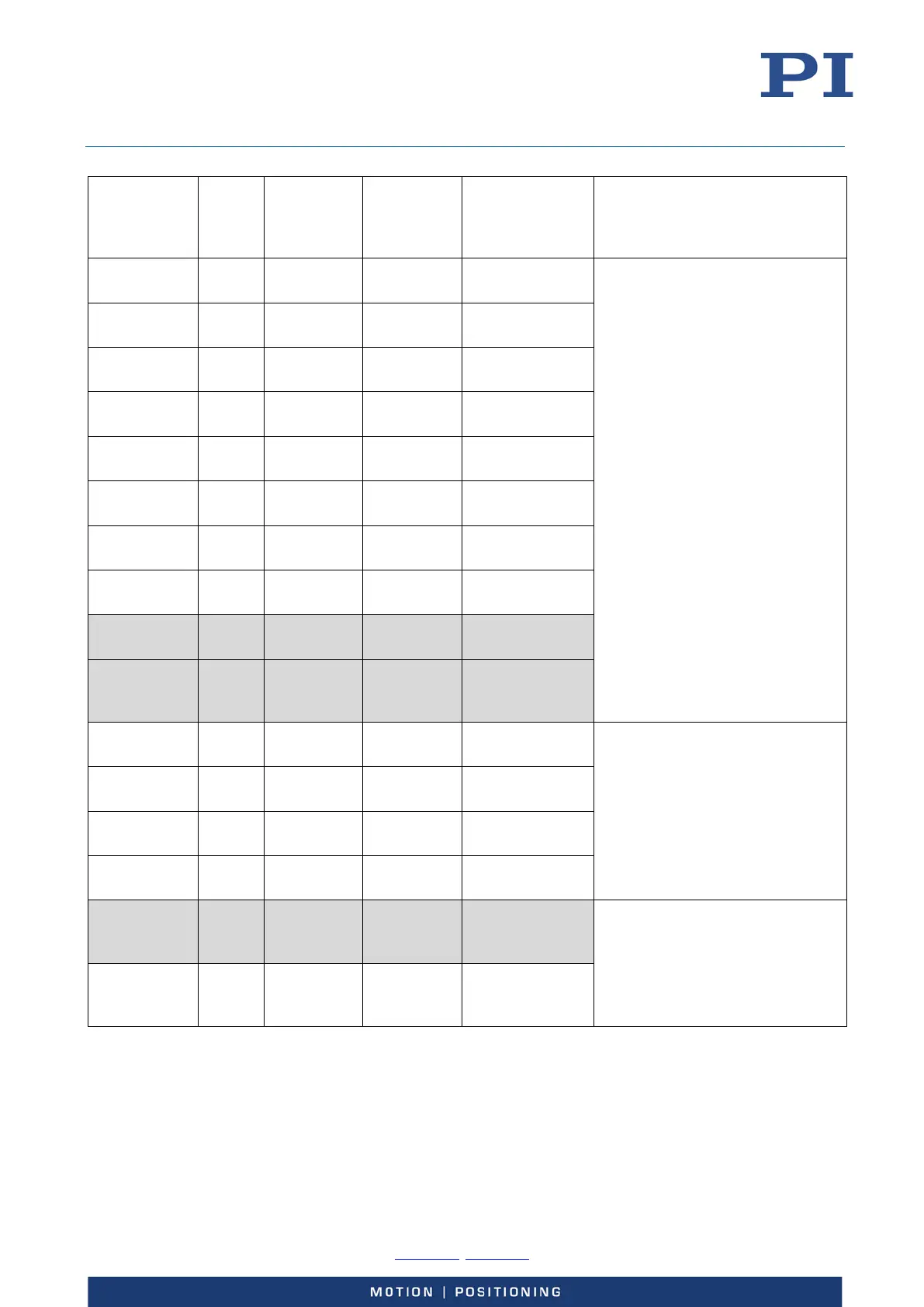
Parameter
ID (hexa-
decimal)
Data
Type
Command
Level for
Write
Access
Item Type Parameter
Name
Description
0x08000100 FLOAT 1 Axis Notch
frequency 1
ID-chip (excluding 0x08000500
and 0x08000600)
Notch filter settings. For details,
see “Notch Filters”, p. 37.
0x08000101 FLOAT 1 Axis Notch
frequency 2
0x08000200 FLOAT 1 Axis Notch Rejection
1
0x08000201 FLOAT 1 Axis Notch Rejection
2
0x08000300 FLOAT 1 Axis Notch
Bandwidth 1
Bandwidth 2
0x08000400 FLOAT 1 Axis Creep factor
T1/sec
0x08000401 FLOAT 1 Axis Creep factor
T2/sec
Open-Loop
0x08000600 INT 1 Axis Notch Filter
Calculation
Method
0x09000000 FLOAT 1 Axis Driving Factor of
Piezo 1
ID-chip
Coefficients of the output matrix.
For details, see “Output
Generation”, p. 34.
Piezo 2
0x09000002 FLOAT 1 Axis Driving Factor of
Piezo 3
0x09000003 FLOAT 1 Axis Driving Factor of
Piezo 4
signal
channel
Type
Usage of the output signal
channels; can only be changed for
output signal channel 4. For
details see „Using the Analog
Output“ (p.
94).
0x0A000004 INT 1 or 3 Output
signal
channel
Select Output
Index