5-60 DA80F/DA95F AddressRight™ Printers Service Manual (SV61962 Rev. A)
5 • Removal and Replacement
DA95F (WF96) - Printer Parts Removal
6. Pivot print head assembly upward by pulling on the blue pivot pin.
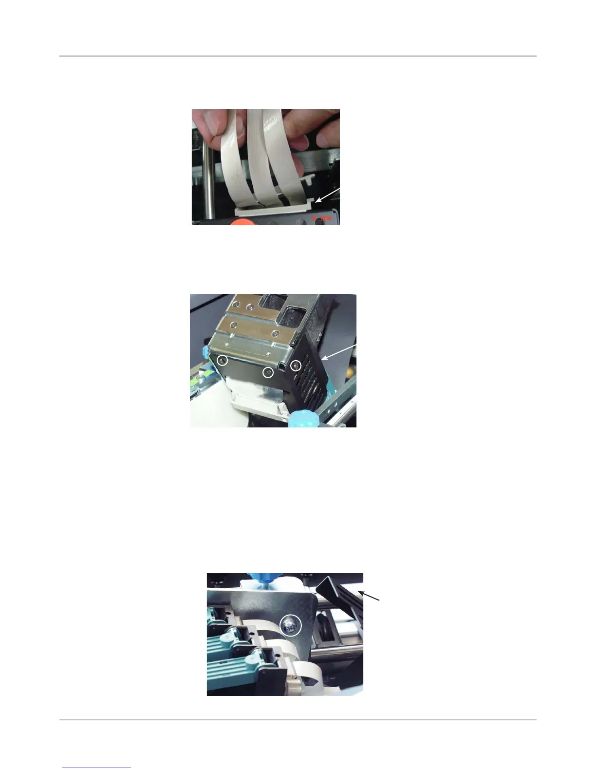
7. Remove three screws (small allen size) for print head metal cover. Slide
metal cover up on print head ribbon cable to gain access to the print
heads.
8. (Optional) - If you want remove the print head assembly to work on it out-
side of the printer, you can do so at this point.
NOTE: If you remove the printhead assembly, however, you need to per-
form the Leveling the Print Head Assembly to Deck adjustment (see sec-
tion 6.5) when finished.
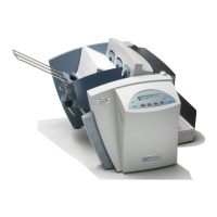
A. Pivot the print head back to normal position. Inside the cover, remove
the large phillips head screw fastening the pivot to the top print head
shaft.
B. Remove print head assembly with print head cables dangling.
Screws for Print
Head Cover
(circled)
Philips Head
Screw for Pivot
(circled)
Cover for Print
Head (Pivoted Up)
Top Print Head Shaft
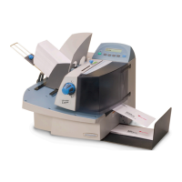
Wire Management
Device on Back of
Print Head Assembly
5. Unclip plastic holder (wire management device) on print head assembly.
5.36 Print
Head Cables
and Print
Head Boards
(continued)