D-4 DA80F/DA95F AddressRight™ Printers Service Manual (SV61962 Rev. A)
Appendix D • Print Head Alignment
Head 1
Head 2
Head 3
1 2 3 4 5 6 7 8 9
1 2 3 4 5 6 7 8 9
ABCDE F GH I J K L MNO
0.25” Gap
Head 1
Head 2
Head 3
1 2 3 4 5 6 7 8 9
1 2 3 4 5 6 7 8 9
ABCDE F GHI J K L MNO
Print Head
Alignment
Procedure
17. When you have scrolled to the appropriate letter value, press Enter to
save the value.
18. Press Menu to go back to the previous screen. Use the plus (+) key
to scroll down to the next adjustment. PRINT HEAD ADJUST screen
displays.
19. Press Enter. The HORIZ ADJ: HDS 2 - 3 screen displays.
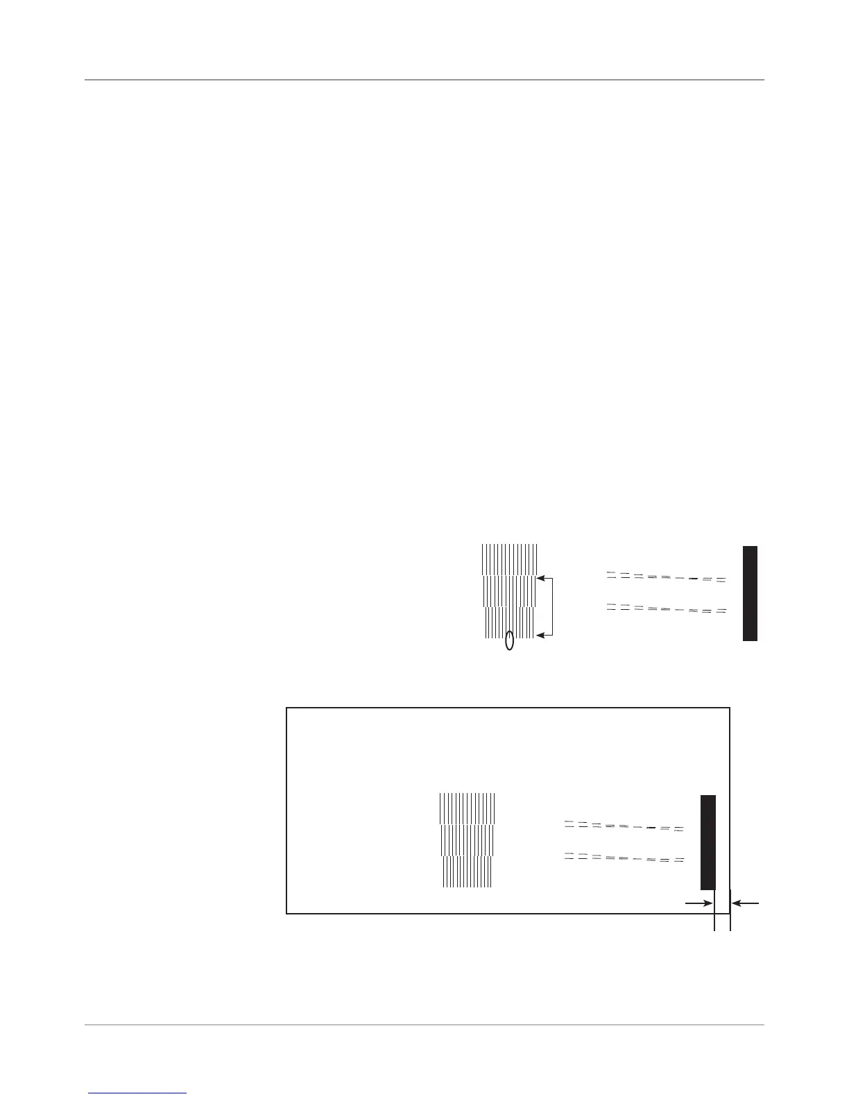
20. Use the plus (+) and minus (-) keys to select the letter value below the
two groups of vertical lines that represent print heads 2 and 3. Select the
pair of vertical lines which most closely form a straight line. In the sample
that follows, the letter value entered would be "h".
21. When you have scrolled to the appropriate letter value, press Enter to
save the value.
22. Press Menu to go back to the previous screen. Use the (+) key to scroll
down to the next adjustment. The MODULE DISTANCE to Sensor screen
displays.
23. Press Enter. The MOD TO SENSOR screen displays.
24. On the test pattern that you printed, there is a solid vertical bar at the far
right edge of the pattern. Carefully measure the distance from the right
edge of the bar to the edge of the media that the test pattern sample
printed on.
• If the gap measures
exactly .25 in (6.35 mm),
then no adjustment is
necessary. Skip to step
27.
• If the gap is not exactly
.25 in (6.35 mm), go to
step 25.