DA80F/DA95F AddressRight™ Printers Service Manual (SV61962 Rev. A)
5-5
Removal and Replacement • 5
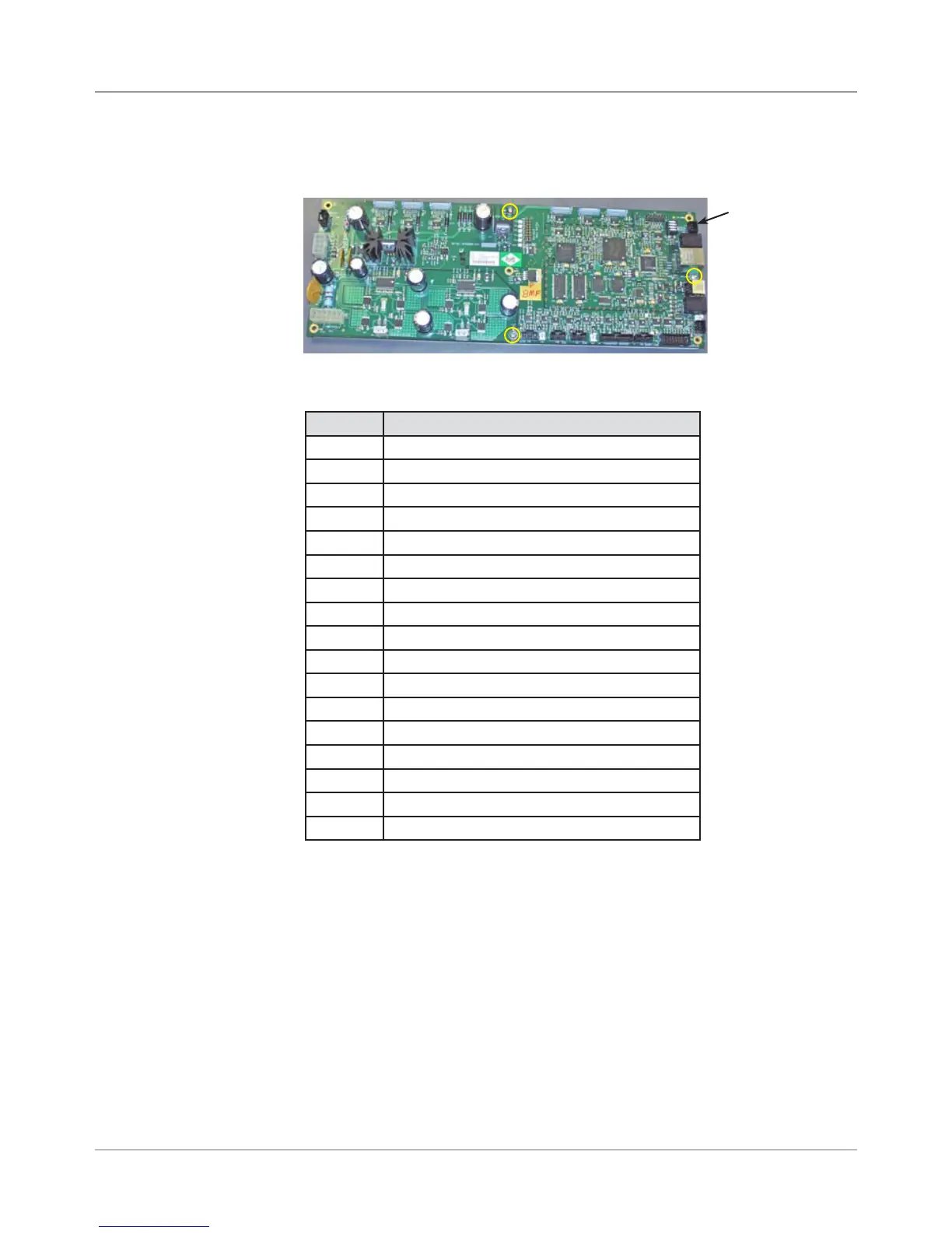
Junction Description
J1 Print Head 1
J2 Print Head 2
J3 Print Head 3
J11 W98x Series Stacker
J12 Third Party Stacker/Conveyor [DA80F only]
J18 LAN
J20 USB
J22 Feeder Sensor Emitter [DA80F only]
J23 Input Power
J24 Feeder Sensor Receiver [DA80F only]
J25 LCD Display
J26 Feeder Motor [DA80F only]
J27 Transport Motor
J31 Feeder Motor Encoder [DA80F only]
J32 Paper Sensor Emitter
J33 Paper Sensor Receiver
J34 Shaft Encoder
7. Install new board and reconnect the cables to the board as shown below.
8. Reinstall in reverse order.
NOTE: Every time the main processor board is changed or removed, the
printer must be powered down and powered on.
IMPORTANT! Be careful when re-connecting the ribbon print head ca-
bles (J1, J2, J3) on the main processor board. Make sure each cable is
aligned straight before fully seating; otherwise, some pins may touch and
cause damage to the print head (Newport) boards inside the print head
assembly upon powering up.
6. Unfasten the three screws (yellow circles in figure below) securing the
processor board to metal ground plate and remove board.
Main Processor
Board
Screws that
hold Board to
Ground Plate
(yellow circles)
DA80F (WF81) Parts Removal
5.3 Main
Processor
Board
(continued)