Planmeca Intra X-ray unit 9
INSTALLATION POSSIBILITIES
Installation manual
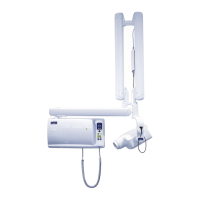
3.2 Control panel assembling alternatives
Standard assembly (see section 4 “STANDARD INSTALLATION TO A WALL” on
page 11)
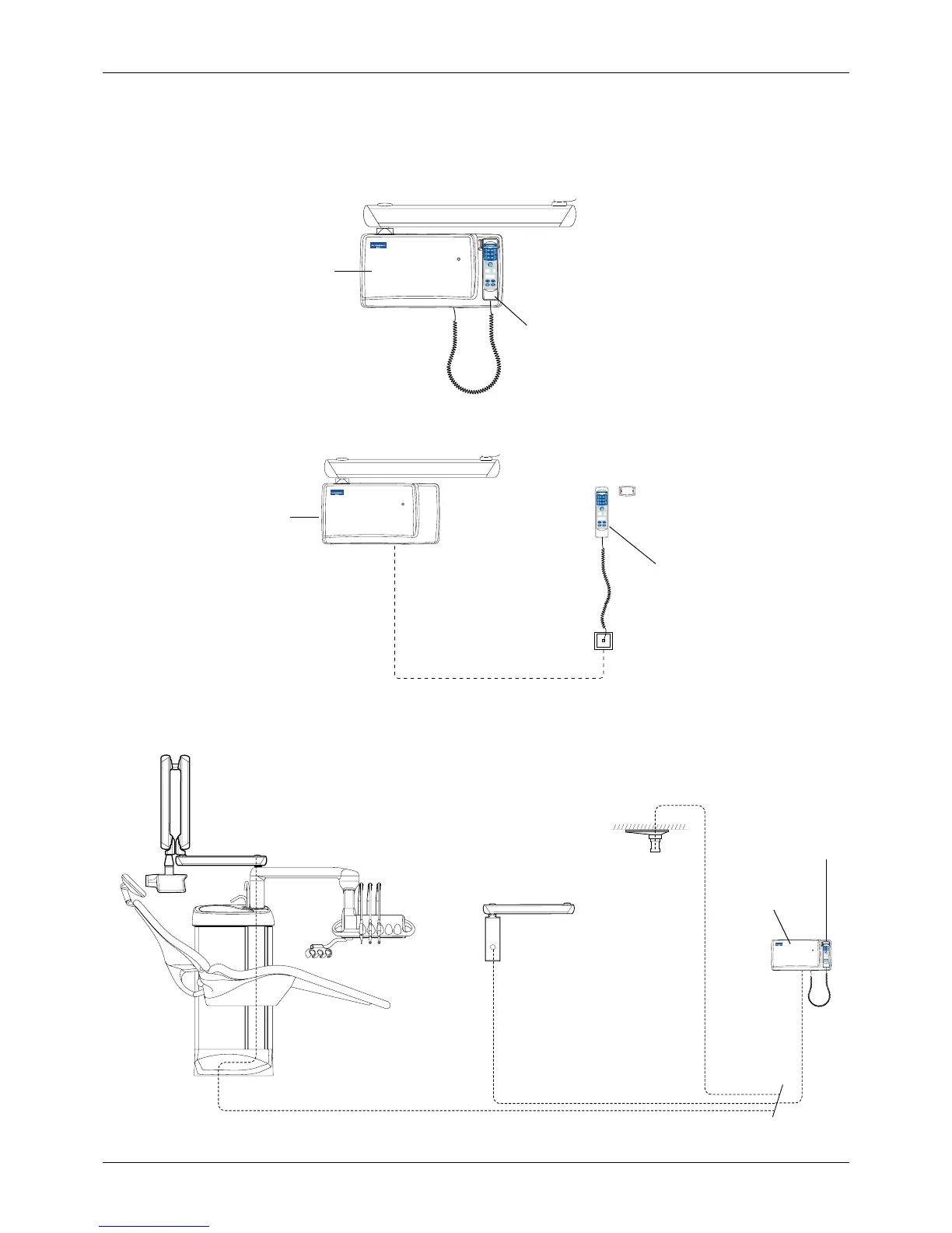
Remote assembly (see section 7 “REMOTE CONTROL PANEL INSTALLATION” on
page 48)
Remote assembly with generator box (see section 6 “ATTACHING THE
GENERATOR BOX WITHOUT THE ADAPTER PLATE” on page 44)
I_front_1.eps
READY
PRET
mA
kV
s
BW
SELECT
MODE
Generator box
Control panel
I_front_2.eps
READY
PRET
mA
kV
s
BW
SELECT
MODE
Generator box
Control panel
Telephone cable
READY
PRET
mA
kV
s
BW
SELECT
MODE
I_front_3.eps
Generator box
Control panel
Single stud plate
Ceiling mounting
Dental unit mounting
Extension cable
 Loading...


