REMOTE CONTROL PANEL INSTALLATION
48 Planmeca Intra X-ray unit
Installation manual
7 REMOTE CONTROL PANEL INSTALLATION
WARNING
Ensure that the power supply is switched off before connecting the cables.
NOTE Use the telephone cable (max. 12 m) between the generator box and the
data wall socket.
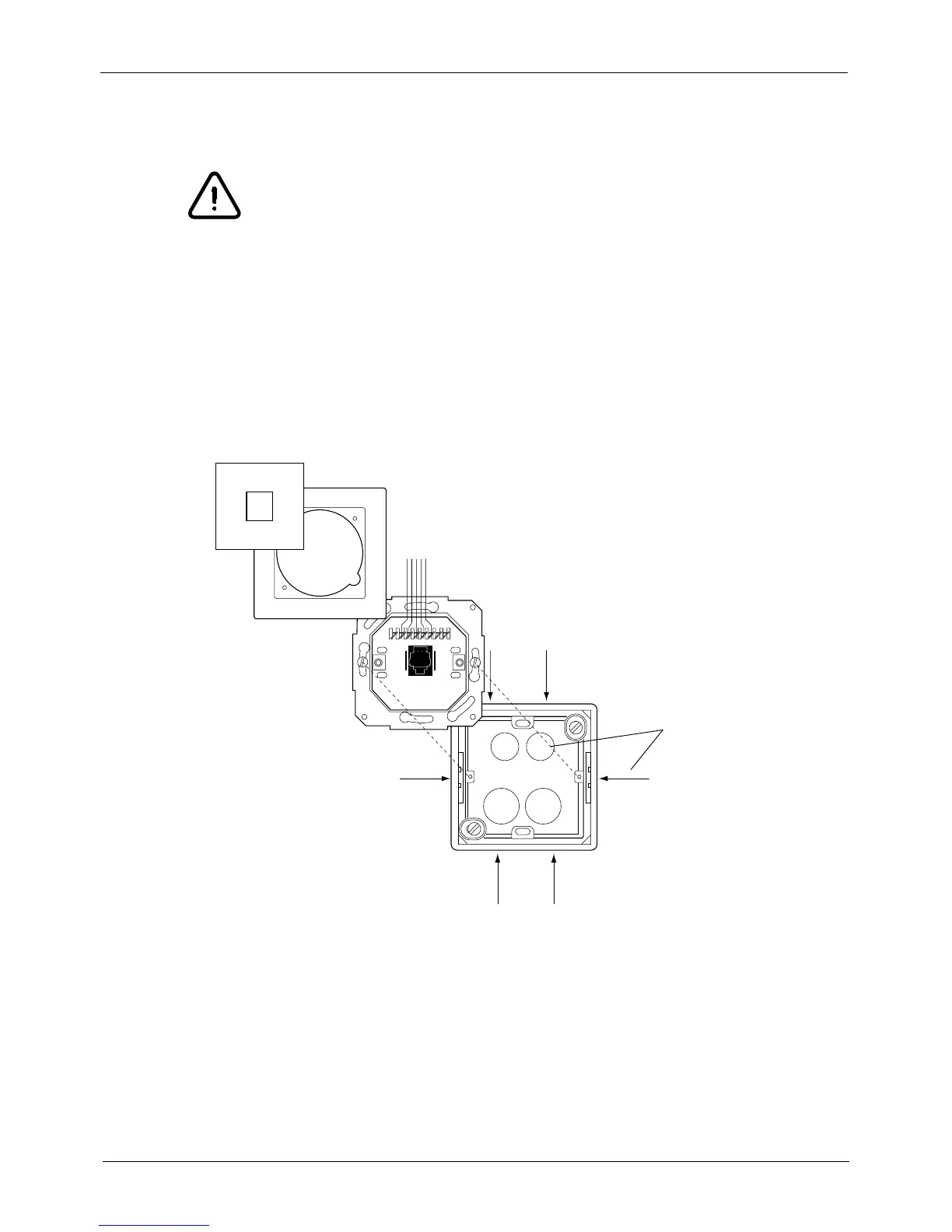
Attach the frame of the data wall socket to the wall with two ø4x30 DIN 7981 screws. If the wall is
made of concrete or brick, drill ø6 mm (0.23 in.), 32...35 mm (1.25 in.) in depth, holes and place the
expansion anchors into them. If the wall is made of wood or plaster, attach the frame to the wall with
two ø4x30 DIN 7981 screws to the wall without drilled holes. Do not use the expansion anchors with
wooden or plaster wall.
Route the telephone cable through the hole on the side or bottom of the frame. Assemble the data
wall socket according to the figure above.
1 2345678
Possible through holes
for the cable
 Loading...


