Planmeca Intra X-ray unit 51
FIXED CONTROL PANEL INSTALLATION
Installation manual
8 FIXED CONTROL PANEL INSTALLATION
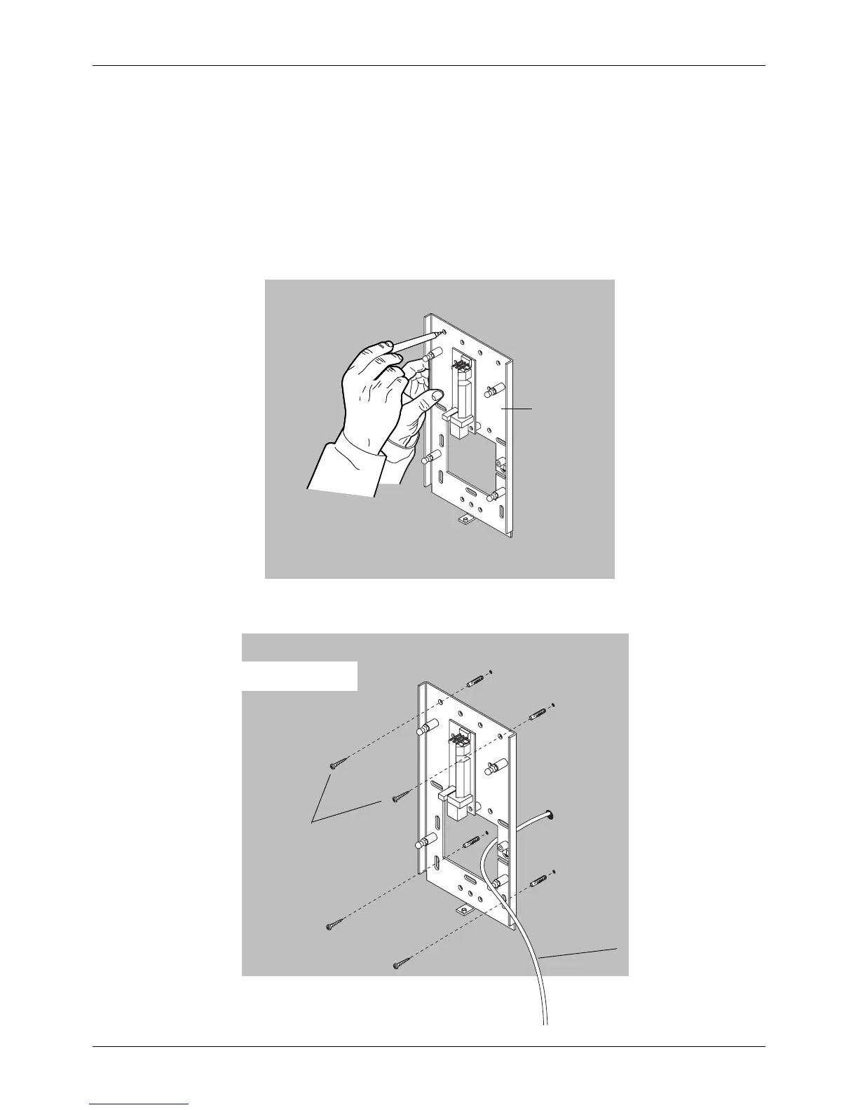
8.1 Attaching the bottom plate
NOTE In case you are using a wall socket, attach the bottom plate according to
instructions given in section 8.2 “Attaching the bottom plate to the wall
socket” on page 52.
Use the bottom plate as a template and mark the positions of the holes for the four attaching screws
to the wall.
If the wall is made of concrete or brick, drill ø6 mm (0.23 in.), 32...35 mm (1.25 in.) in depth, holes
and place the expansion anchors into them. If the wall is made of wood, attach the screws to the
wall without drilled holes. Do not use the expansion anchors with wooden or plaster wall.
Intra_box1.eps
Bottom plate
4x
Intra_box2.eps
Telephone cable
Expansion anchor
Use 4 attaching screws
Note: Do not use expansion
anchors with wooden/plaster wall.
ø4x30 DIN 7981
 Loading...


