STANDARD INSTALLATION TO A WALL
20 Planmeca Intra X-ray unit
Installation manual
4.6 Connecting the cables
WARNING
Ensure that the power supply is switched off before connecting the cables.
Arm cable
Connect the grounding lead of the arm cable to the grounding point located on the right side of the
generator assembly. Connect the control leads of the arm cable (6-pole connector) to the terminal
P8 on the generator PCB. Connect the power leads (3-pole connector) of the arm cable to the termi-
nal P1 on the generator PCB. Snap the ferrite to the arm cable as shown on the figure on next page.
Mains cable (concealed wiring)
In the case that mains voltage is supplied via concealed wiring route the mains cable between the
adapter plate and the generator assembly.
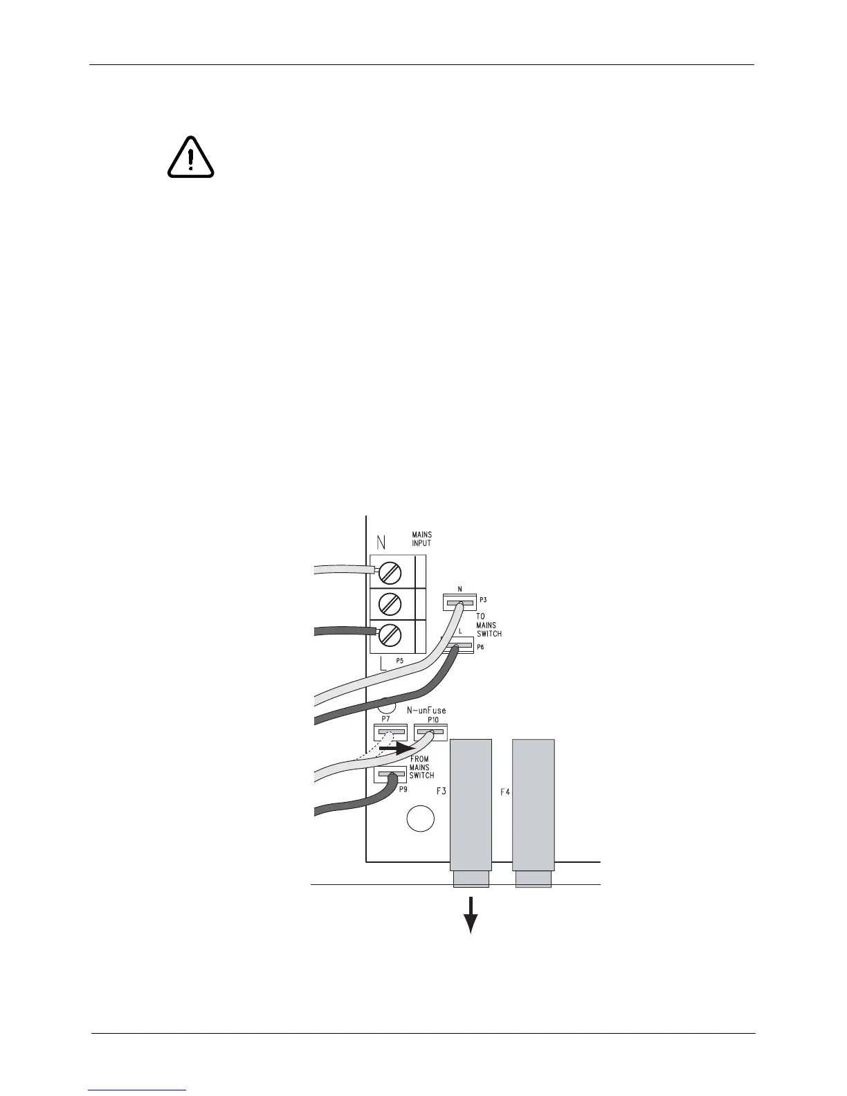
Connect the grounding lead to the grounding point next to the mains switch. Connect the neutral
wire to the mains input terminal (P5) marked N. Connect the live wire to the mains input terminal
(P5) marked L.
Generator PCB version -C or later (from X-ray unit’s serial number IXRF58018): When the con-
cealed wiring is used the cable coming from the ON/OFF switch to the connector P7 must be moved
to the connecto P10. Also the fuse F3 must be removed.
Remove Fuse F3
Neutral
Line
Blue
Brown
Blue
Brown
 Loading...


