STANDARD INSTALLATION TO A WALL
16 Planmeca Intra X-ray unit
Installation manual
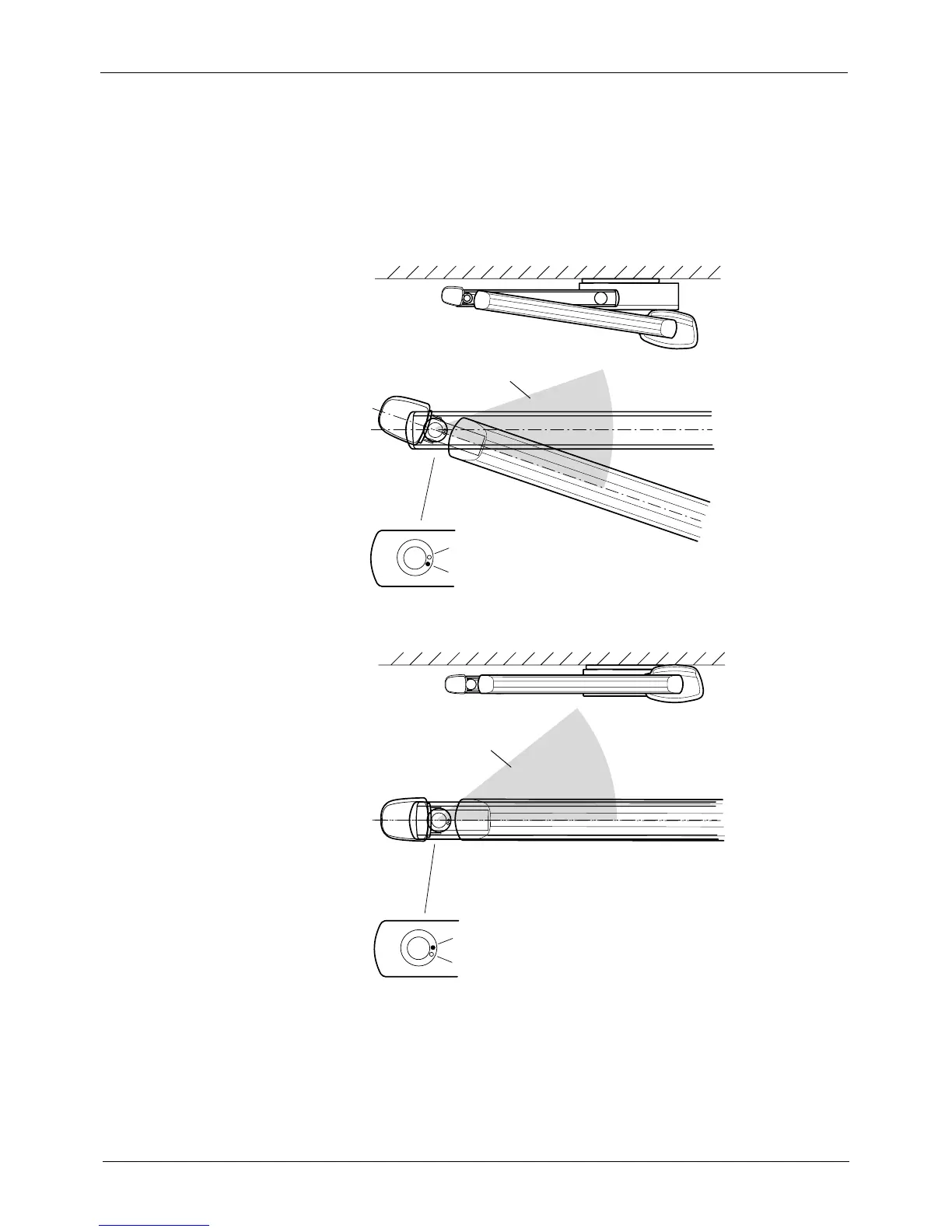
4.3 Changing the bracket arm movement area
NOTE Normally the bracket arm does not turn above the extension arm, but the
arm movement area can be changed by moving the limiting pin on the
extension arm shaft housing. The factory preset and modified movement
areas are shown on the figures below. THE LIMITING PIN POSITION CAN
BE CHANGED BUT THE PIN MUST NOT BE REMOVED.
NOTE When the modified area is used the tube head can hit the extension arm.
Be careful not to knock the tube head against the arm.
Factory preset movement area
Empty opening
Pin
intra1.eps
Arm movement obstructed
Pin
Empty opening
intra2.eps
Arm movement obstructed
Modified movement area
 Loading...


