Planmeca Intra X-ray unit 11
STANDARD INSTALLATION TO A WALL
Installation manual
4 STANDARD INSTALLATION TO A WALL
WARNING
Ensure that the power supply is switched off before installing the
Planmeca Intra X-ray unit.
4.1 Attaching the standard adapter plate to wall
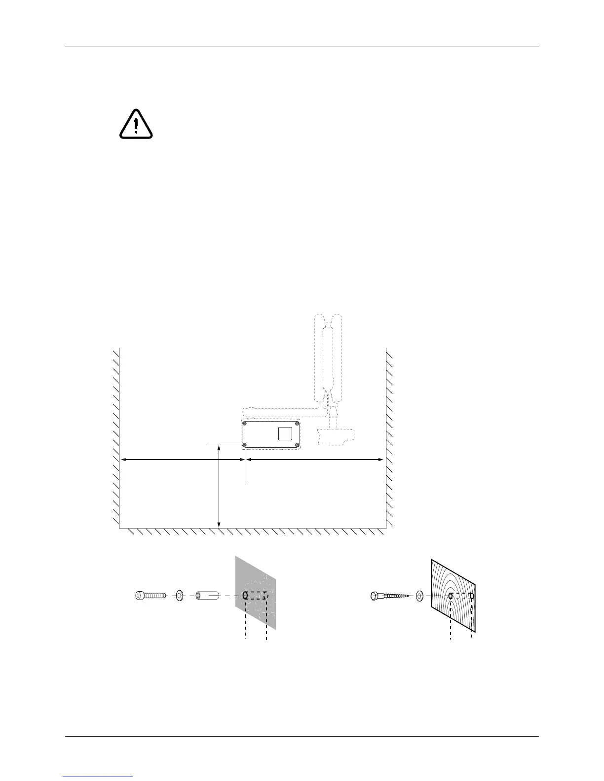
The Planmeca Intra X-ray unit must be positioned in accordance with the information given in the
installation pattern supplied with the unit. The X-ray unit should be positioned within the reach of the
power supply cable (3m) (118 in.). In the case that concealed wiring is used, the cable outlet should
be positioned next to (on the right-hand side) the adapter plate.
The wall plate is attached to the wall according to the instructions given in next pages. If the wall is
made of concrete or brick, use the M8x30 DIN 912 screws and the expansion anchors. If the wall is
made of wood or plaster, use the ø8x80 DIN 571 lag screws. Do not use the expansion anchors with
wooden or plaster wall. See figure below.
IR7.eps
Wall made of
concrete or stone
Wooden or plaster wall
ø10 mm (0.4 in.)
32…35 mm (1.25 in.)
ø5mm (0.2 in.)
55…60 mm (2.2 in.)
Height 1120mm (44 in.)
Width min. 1100mm
(min. 43 in.)
Width min. 1000mm
(min. 39 in.)
The minimum widths
stated are measured using
the 535 mm (21.1 in.) long
extension arm.
For 385 mm (15.2 in.)
extension arm subtract 150
mm (5.9 in.) from the mini-
mum width.
For 760 mm (30.0 in.)
extension arm add 225 mm
(8.9 in.) to the minimum
width.
For 835 mm (32.9 in.)
extension arm add 300 mm
(12 in.) to the minimum
width.
M8x30 DIN 912 ø8x80 DIN 571
 Loading...


