STANDARD INSTALLATION TO A WALL
12 Planmeca Intra X-ray unit
Installation manual
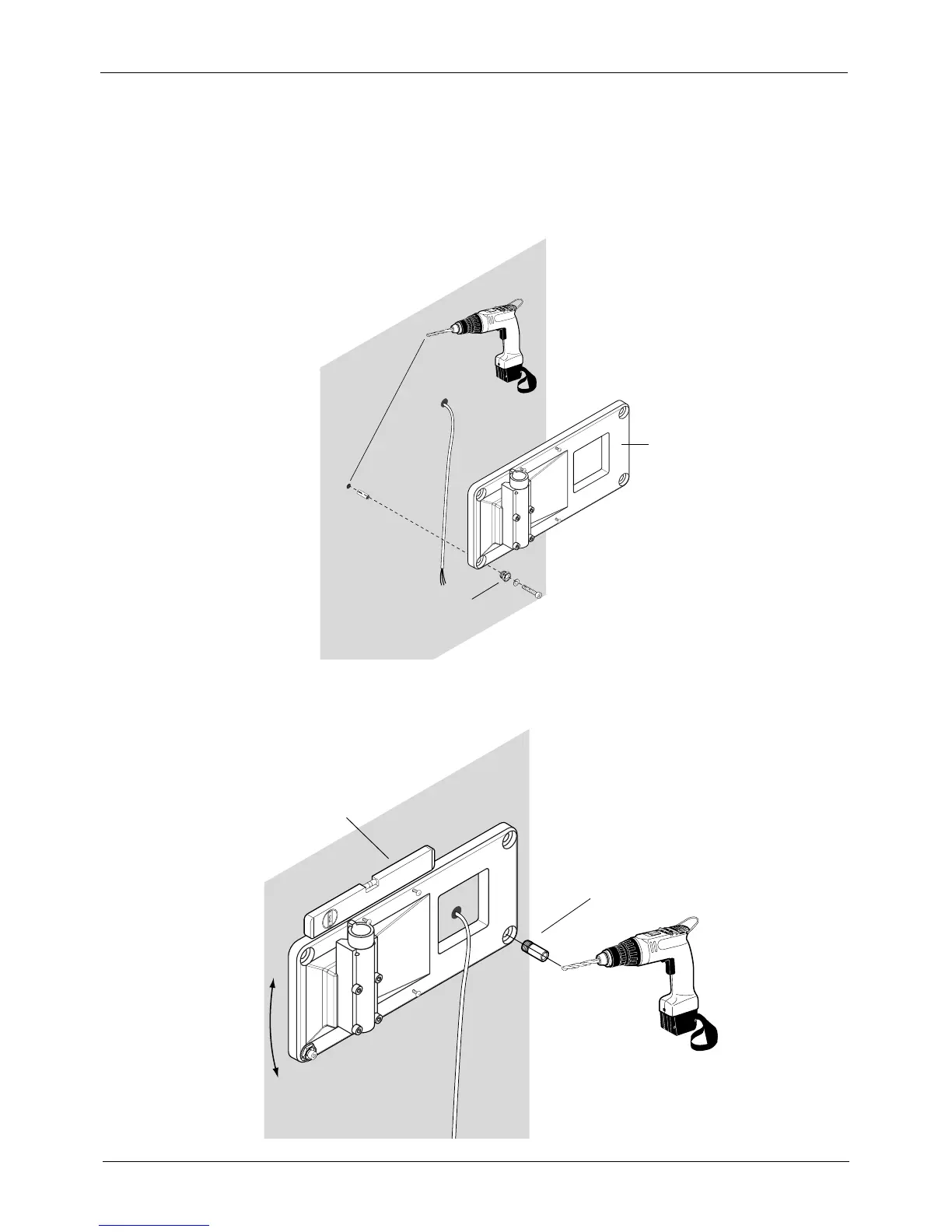
Attaching alternative 1 (recommended for concrete or brick wall)
Mark the position of the left lower mounting hole to the wall on the height of 1120 mm (44 in.). Drill
one ø10mm (0.4 in.), 32...35 mm (1.25 in.) in depth, hole and place the expansion anchor into it.
Make sure that the end of the anchor is under the wall surface, but not more than 5 mm. Hit the
wedge of the anchor firmly to the bottom of the hole. Remove the adjustment nuts from the three
other mounting holes. Attach the adapter plate to the wall with one of the fastening screws and
adjust the plate exactly to horizontal position.
Insert the drilling tool to one of the holes and drill the second hole using the drilling tool as a guide.
Unscrew the drilling tool and insert the second expansion anchor as described above, replace the
adjustment nut and attach the screw.
1
1
1
2
3
4
5
6
Ins1.eps
Adjustment nut
Adapter plate
Ins2.eps
1
2
3
4
5
6
2
3
5
4
Drilling tool, part number 6525091
Spirit level
 Loading...


