OTHER INSTALLATION ALTERNATIVES
38 Planmeca Intra X-ray unit
Installation manual
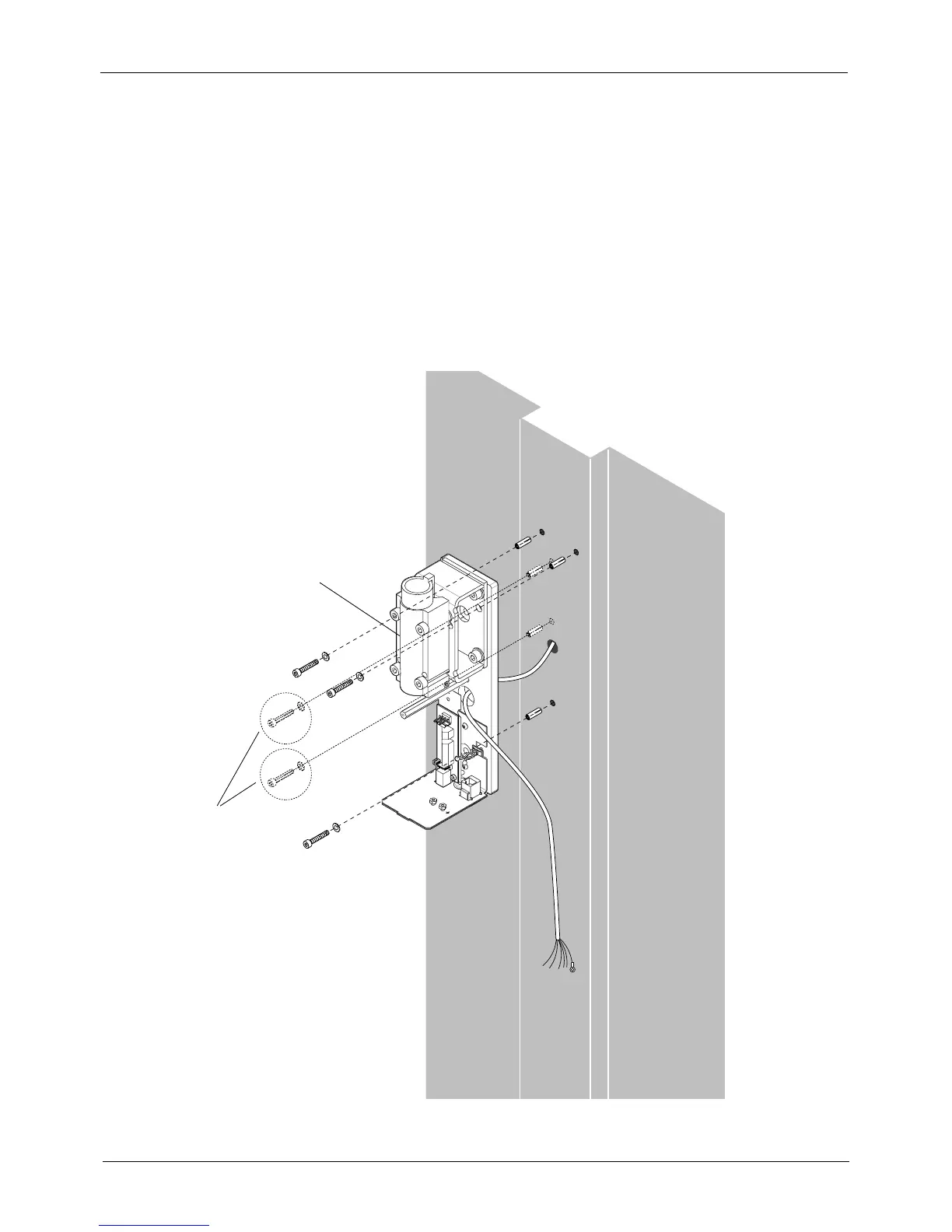
5.3 Single stud installation
NOTE Use the single stud assembling plate when you are installing the Planmeca
Intra to a cabinet, to an end of a wall, or to a single stud (plaster) wall.
Use the installation pattern or the single stud adapter plate as a template and mark the positions
where the holes for the attaching screws will be drilled.
If the wall is made of concrete or brick, drill ø10mm (0.4 in.), 32…35 mm (1.25 in.) in depth, holes
and place the expansion anchors into them. If the wall is made of wood, drill ø5 mm (0.2 in.), 55…60
mm (2.2 in.) in depth, holes for the attachment screws. Do not use the expansion anchors with
wooden wall.
Attach the adapter plate to the wall with at least three M8x80 DIN 571 screws and the ø8.4 DIN 125
washers. Route the extension cable through the opening on the adapter plate.
Assemble the bracket arm to the extension arm, refer to the section 4.2 “Assembling the arm” on
page 15.
I_8A.ep
 Loading...


