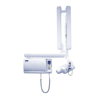
INSTALLATION POSSIBILITIES
4 Planmeca Intra X-ray unit
Installation manual
3 INSTALLATION POSSIBILITIES
3.1 Mounting alternatives
NOTE The Planmeca Intra X-ray unit can be installed in several ways. Read these
installation instructions carefully, because some installation accessories
are optional, and are not included in the standard delivery. Make sure that
required accessories are available before starting the installation.
NOTE The following cables are used in some installations described in this sec-
tion:
EXTENSION CABLE:
1pcs. protective earth min. 1.0 mm
2
AWG 18
4 pcs. signal wires min. 1.0mm
2
AWG 18
4 pcs. signal wires min. 0.5 mm
2
AWG 20
rated 300 V, flexible
TELEPHONE CABLE:
ordinary 6-pole telephone cable AWG 24.
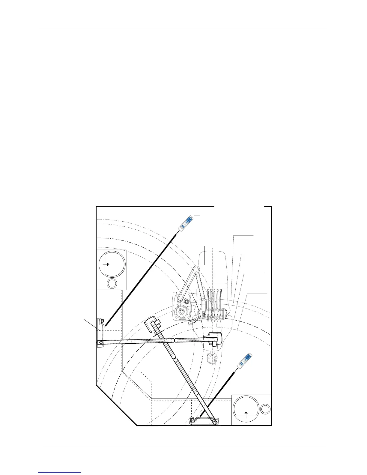
Standard wall mounting in treatment room (see section 4 “STANDARD
INSTALLATION TO A WALL” on page 11)
S
C
D
A
B
&&
&
&
R
EA
D
Y
PRET
mA
kV
s
B
W
S
E
L
E
C
T
M
O
D
E
R
EA
D
Y
PRET
mA
kV
s
B
W
S
E
L
E
C
T
M
O
D
E
IR1_1.eps
extension
arm 835mm
r=1975
extension
arm 535mm
r=1675 (std)
extension
arm 385mm
r=1525
extension
arm 760mm
r=1900
Dental unit
Generator box
Control panel
 Loading...


