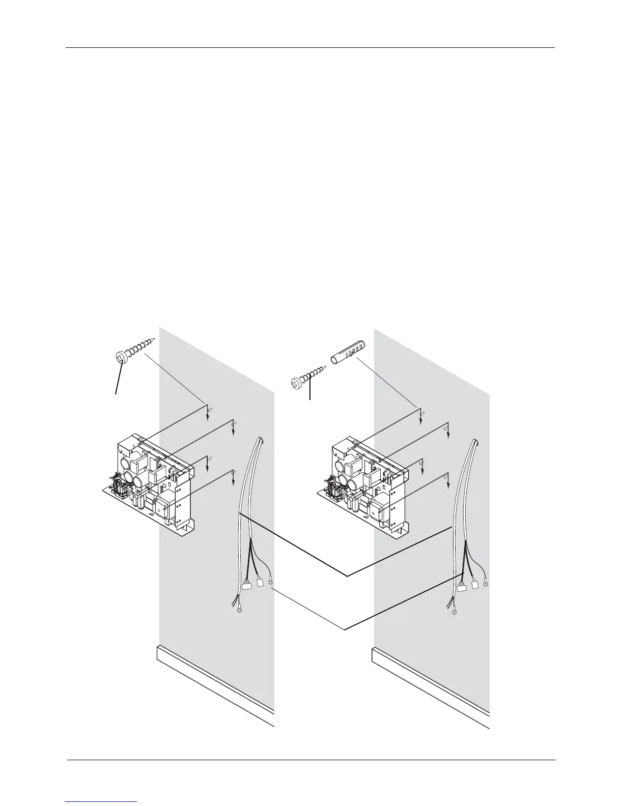
ATTACHING THE GENERATOR BOX WITHOUT THE ADAPTER PLATE
44 Planmeca Intra X-ray unit
Installation manual
6 ATTACHING THE GENERATOR BOX WITHOUT THE
ADAPTER PLATE
NOTE The generator box is attached to the wall without adapter plate in ceiling,
single stud and dental unit installations.
NOTE Use the extension cable supplied with the unit between the X-ray unit and
generator box. Note, that the connectors of the cable must be connected to
the generator box and the cable wires to the Extension cable PCB.
In the case that concealed wiring is used, the mains cable and extension cable outlet should be
positioned next to (on the right-hand side) the adapter plate.
Use the generator assembly as a template and mark the positions of the holes for the four attaching
screws to the wall. If the wall is made of concrete or brick, drill ø6 mm (0.23 in.), 32...35 mm (1.25
in.) in depth, holes and place the expansion anchors into them. If the wall is made of wood or plas-
ter, attach the screws to the wall without drilled holes. Do not use the expansion anchors with
wooden or plaster wall.
Ins8APSU2.eps
Concrete (brick) wall
Wooden (plaster) wall
Power cable
Extension cable
ø4x30 DIN 7981
ø4x30 DIN 7981
Expansion anchor
 Loading...


