Planmeca Intra X-ray unit 45
ATTACHING THE GENERATOR BOX WITHOUT THE ADAPTER PLATE
Installation manual
Insert the screws to the holes and slip the generator assembly under the heads of the screws.
WARNING
Ensure that the power supply is switched off before connecting the cables.
In the case that mains voltage is supplied via concealed wiring route the mains cable as shown on
the figure below.
NOTE In case the X-ray units own power supply cable and the strain reliefer are
removed from the generator assembly (mains voltage is supplied via con-
cealed wiring), cover the opening with a plug supplied with the X-ray unit.
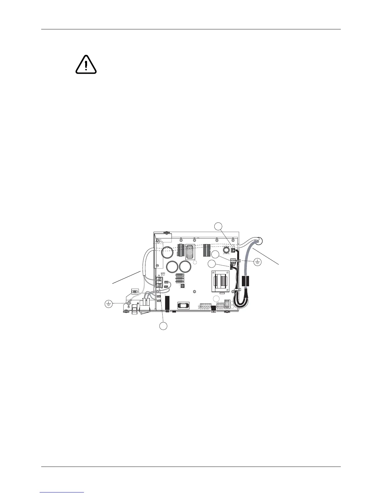
Connect the grounding lead of the power cable to the grounding point next to the mains switch. Con-
nect the neutral wire to the mains input terminal (P5) marked N. Connect the live wire to the mains
input terminal (P5) marked L.
Connect the grounding lead of the extension cable to the grounding point located on the right side of
the generator assembly. Connect the control leads of the cable (6-pole connector) to the terminal P8
on the generator PCB. Connect the power leads (3-pole connector) of the cable to the terminal P1
on the generator PCB. Snap the ferrite to the extension cable as shown on the figure below.
Ins10APSU2.eps
P1
P8
P14
P5
Extension cable
Power cable
 Loading...


