STANDARD INSTALLATION TO A WALL
14 Planmeca Intra X-ray unit
Installation manual
Attaching alternative 2 (for wooden wall, not recommended for concrete wall)
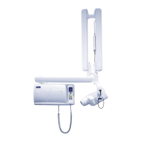
Use the installation pattern as a template and mark the positions where the holes for the four attach-
ing screws will be drilled. Use a spirit level to ensure that the adapter plate will be level.
If the wall is made of concrete or brick, drill ø10mm (0.4 in.), 32…35 mm (1.25 in.) in depth, holes
and place the expansion anchors into them. Attach the adapter plate to the wall with the four M8x30
DIN 912 screws and the ø8.4 DIN 125 washers.
If the wall is made of wood or plaster, drill ø5 mm (0.2 in.), 55…60 mm (2.2 in.) in depth, holes for
the attachment screws. Do not use the expansion anchors with wooden or plaster wall. Attach the
adapter plate to the wall with the four ø8x80 DIN 571 lag screws and the ø8.4 DIN 125 washers.
You can use two adjustment plates under the adapter plate.
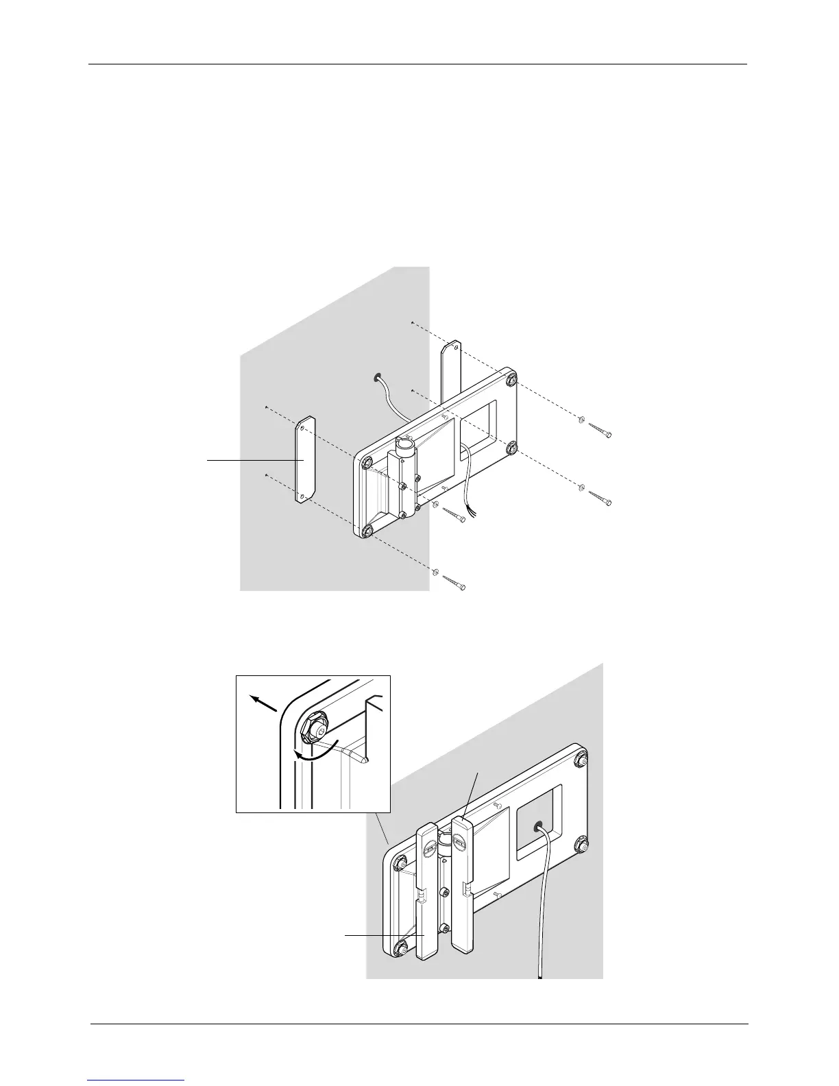
Use the adjustment nuts with the screws at each corner of the adapter plate. Adjust the wall adapter
bearing to vertical position by opening slightly the mounting screws and turning the adjustment nuts
to required position. The wall adapter moves towards the wall when turning the nut counterclock-
wise.
Finally, tighten all the mounting screws.
Ins16.eps
Adjustment plate
(optional)
Ins4.eps
Adjust
Check
 Loading...


