Planmeca Intra X-ray unit 15
STANDARD INSTALLATION TO A WALL
Installation manual
4.2 Assembling the arm
CAUTION
Care must be taken when assembling the arm for not to damage the arm
cable.
NOTE Normally the bracket arm does not turn above the extension arm. In case
you need to change the movement area of the bracket arm, refer to section
4.3 “Changing the bracket arm movement area” on page 16.
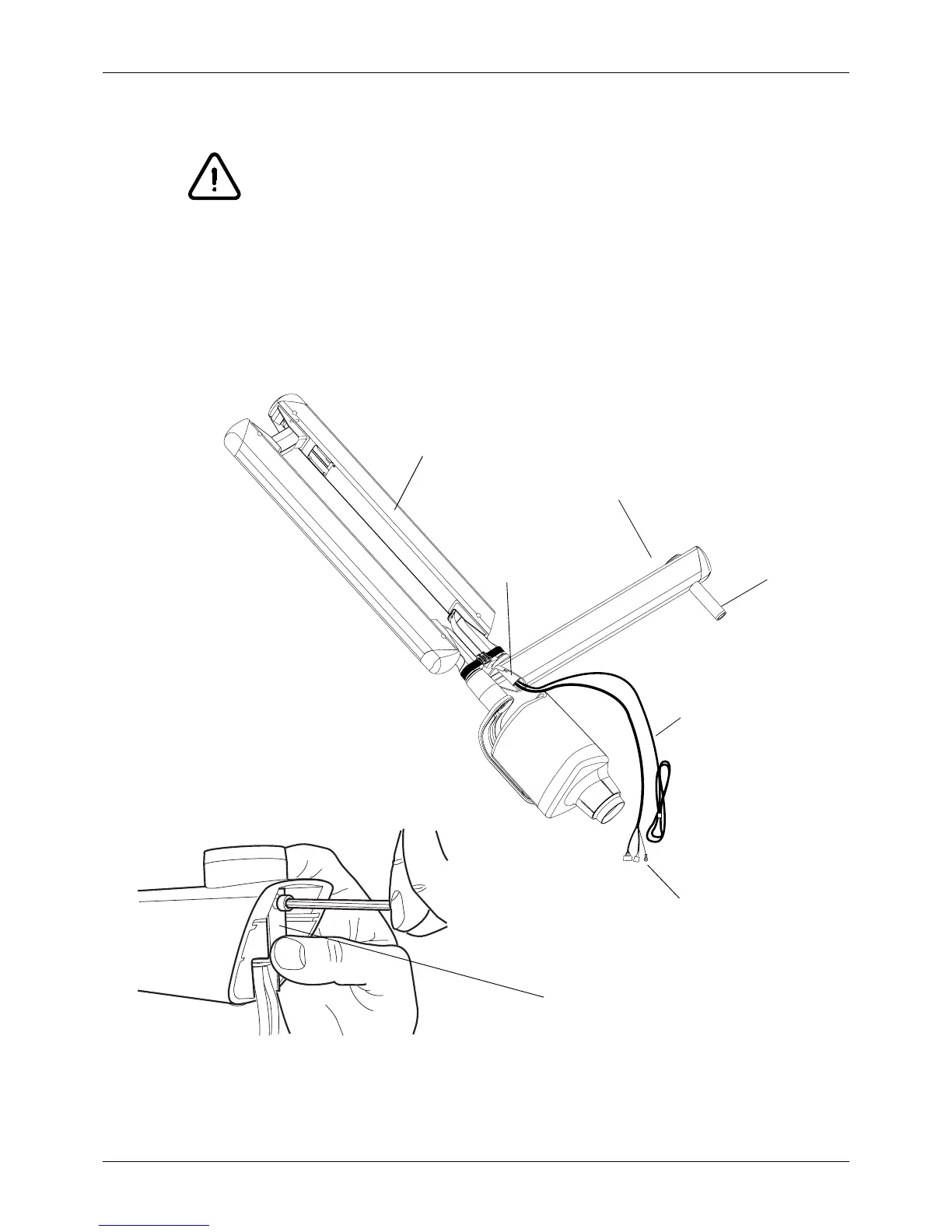
Route the arm cable and the Dixi interconnection cable through the extension arm shaft housing.
Assemble the bracket arm to the extension arm by pushing the bracket arm shaft into the housing.
Secure the bracket arm with the locking plate. Route the cables through the extension arm and arm
shaft. Place the cover plug back to the end of the extension arm.
Unit_arm2_00.eps
Extension arm
Arm cable
Arm shaft housing
Bracket arm
 Loading...


