Bookletmaker SR 85 February 2001PAGE
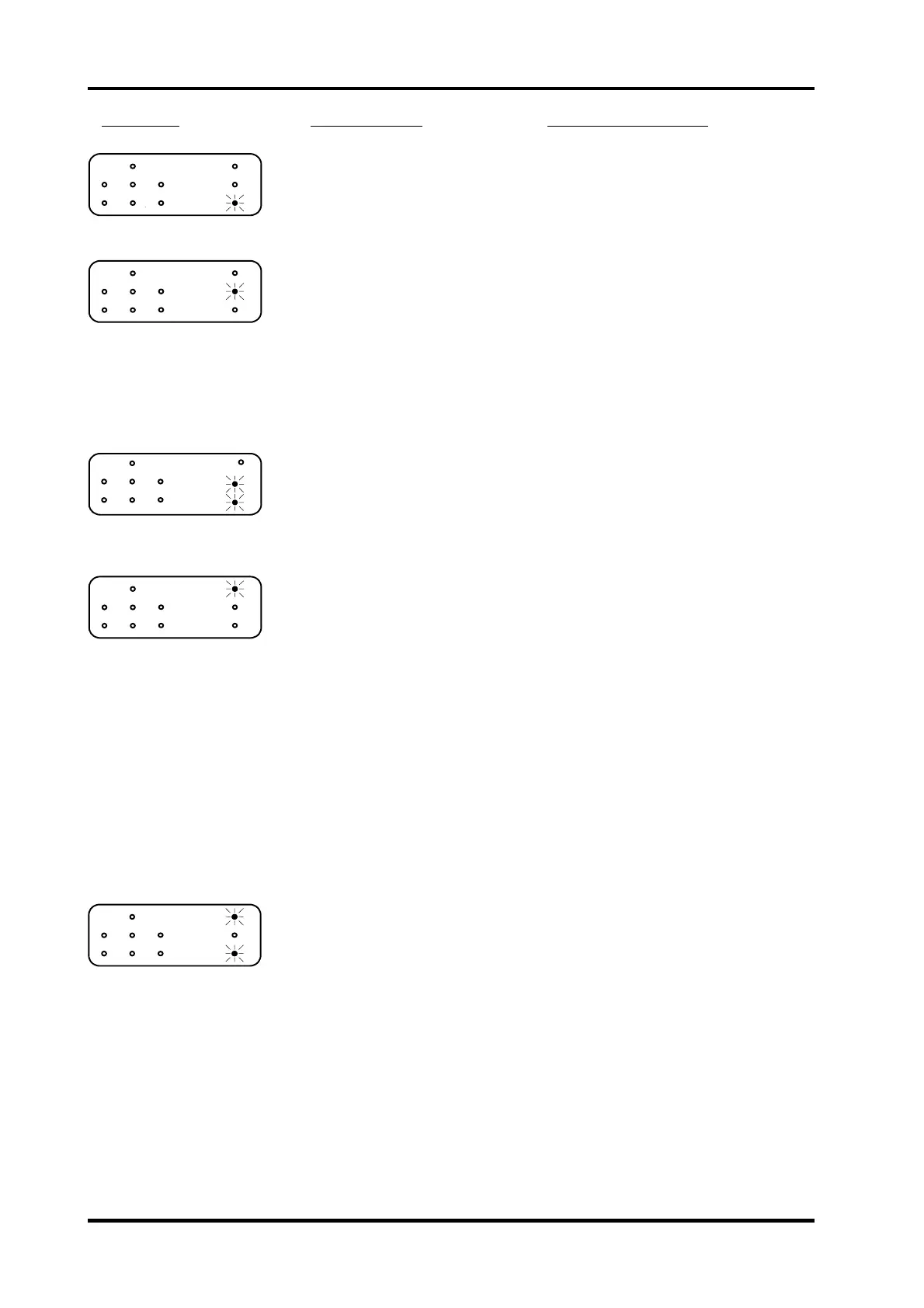
Fault code Possible cause
Fault isolating / repair
1. EEPROM error
EEPROM values incorrect. Reset the EE-prom according to PRG 6.1.
EEPROM defective. Replace the controller PCB.
2. 36 VDC error
Interlock switch SW 5 activated. See fault code 5.
Rectifier REC 1 defective. Replace Rectifier.
Transformer T 1 defective. Replace Transformer.
Capacitor C 1 defective. Replace Capacitor.
Wires defective. Check the wires for an open circuit using
a voltmeter. Measure from 3, 4 and 5 on
connector J8 to the capacitor.
Controller PCB defective. Replace controller PCB.
3. 24 VDC error
Controller PCB defective. Replace controller PCB.
4. Interlock switch SW 5,
activated.
Top cover open or Interlock
switch not activated.
Close the Top cover or pull out the
Interlock bypass switch actuator.
Top cover misadjusted. Check/Adjust the Top cover according to
REP 1.2.
Micro switch defective. Disconnect the wires from the switch.
Check the function of the switch using a
voltmeter. Check both Interlock micro
switch and Interlock bypass micro switch.
Wires defective. Disconnect the wires from the switch.
Check the wires for an open circuit using
a voltmeter. Measure from 10C and 17A
on connector J1 to the Interlock switch
and 10C and 12A to the bypass switch.
Controller PCB defective. If checks above is good, replace the
controller PCB.
5. Stapler home position
switch SW 1, not
activated
.
Stapler motor in faulty position.
Stapler home position
misadjusted.
Switch off the power and switch on the
power again.
Check/Adjust the Stapler home position
according to REP 3.5.
Micro switch defective. Disconnect the wires from the switch.
Check the function of the switch using a
voltmeter.
Wires defective. Check that the voltage between TP5 on
the controller PCB and common ground is
less than 0.9 VDC when the switch is
activated and greater than 2.2 VDC when
the switch is inactivated.
Controller PCB defective. If checks above is good, replace the
controller PCB.
FIP 8.1 Self diagnostic system control, Fault code table
8.1.2