Bookletmaker SR 85 February 2001PAGE
Fault code Possible cause
Fault isolating / repair
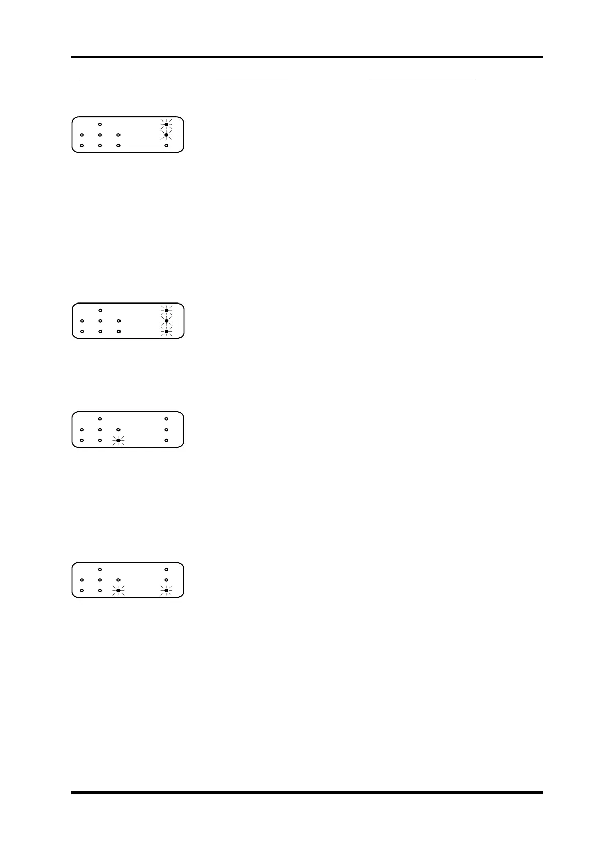
6. Fold knife motor home
position sw itch SW 2,
not activated.
Fold knife motor in faulty position.
Fold knife home position
misadjusted.
Switch off the power and switch on the
power again.
Check/Adjust the Fold knife home position
according to REP 4.4.
Micro switch defective. Disconnect the wires from the switch.
Check the function of the switch using a
voltm eter.
Wires defective. Check that the voltage between TP4 on
the controller PCB and common ground is
less than 0.9 VDC when the switch is
activated and greater than 2.2 VDC when
the switch is inactivated.
Controller PCB defective. If checks above is good, replace the
controller PCB.
7. Side jogger home
position sensor SEN 6,
faulty.
Sensor defective.
Check that the voltage between TP3 on
the controller PCB and common ground is
less than 0.9 VDC with the sensor
blocked and greater than 2.2 VDC with
the sensor unblocked.
Wires defective. Disconnect the sensor connector. Check
the wires for an open circuit using a
voltmeter. Measure from 30A and 30C on
connector J1 to the sensor connector.
Measure from 30A and 4C on connector
J1 to the sensor connector.
Controller PCB defective. Replace the controller PCB.
8. Edge stapling sensor
SEN 3, activated.
Paper is blocking the sensor.
Sensor defective.
Remove the paper.
Check that the voltage between TP7 on
the controller PCB and common ground is
less than 0.9 VDC with the sensor
blocked and greater than 2.2 VDC with
the sensor unblocked.
Wires defective. Disconnect the sensor connector. Check
the wires for an open circuit using a
voltmeter. Measure from 26C and 26A on
connector J1. Meassure from 2C and 8A
on connector J1.
Controller PCB defective. If checks above is good, replace the
controller PCB.
9. Saddle stapling sensor
SEN 1, activated.
Paper is blocking the sensor.
Sensor misadjusted.
Remove the paper.
Check/Adjust the Saddle stapling sensor
according to REP 3.7.
Sensor defective.
Check that the voltage between TP1 on
the controller PCB and common ground is
greater than 2.2 VDC with the sensor
blocked and less than 0.9 VDC with the
sensor unblocked.
Wires defective. Disconnect the sensor connector. Check
the wires for an open circuit using a
voltmeter. Measure from 32C, 32A on
connector J1. Measure from 1C and 23A
on connector J1.
Controller PCB defective. If checks above is good, replace the
controller PCB.
Continue FIP 8.1 Self diagnostic system control, Fault code table
8.1.3