DE-9 CONNECTOR
(ON COMMUNICATIONS
PANEL OF
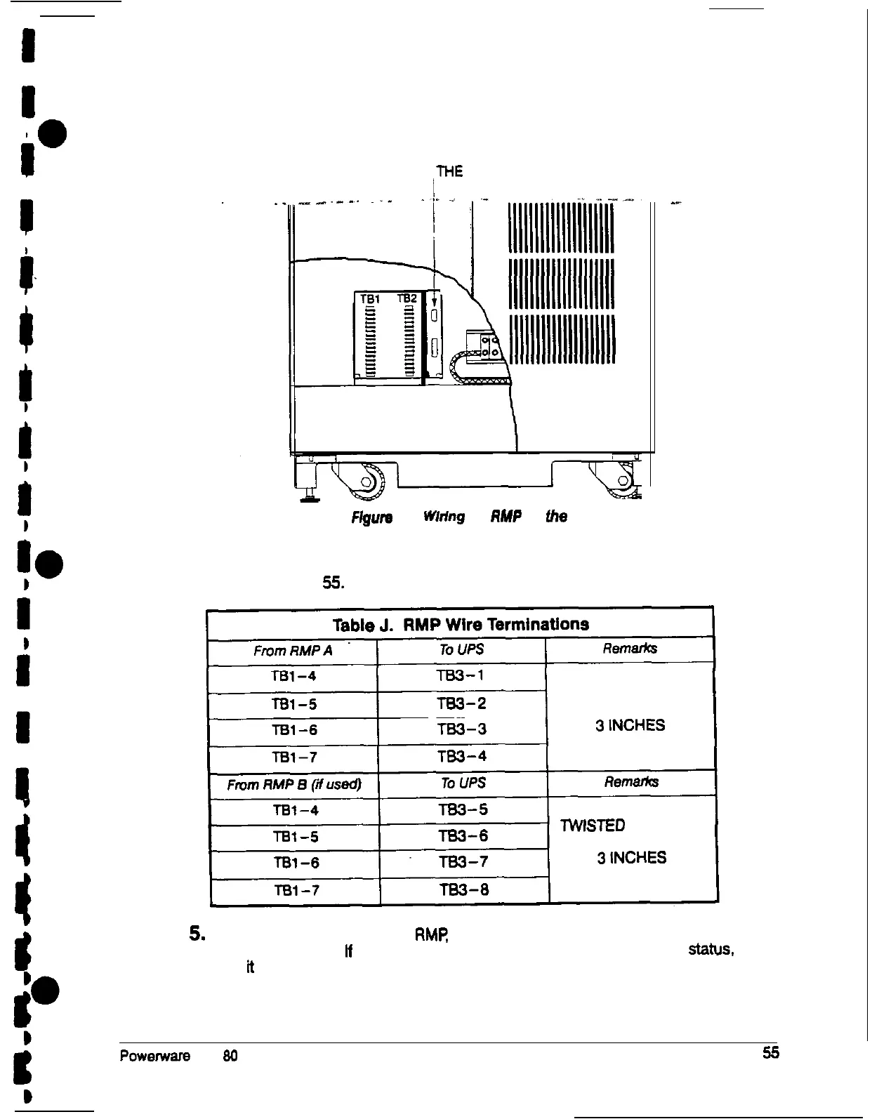
THE
UPS)
Flgufe
37.
Whfng
an
RMP
to
the
UPS
4. Connect the RMP wiring to the terminal block using the terminations shown in
Table J on page 55.
TWISTED WIRES (4)
l-2 TURNS PER
lWlSTED WIRES (4)
l-2 TURNS PER
5.
To check the operation of the RMR ensure that the UPS is supplying the load via
inverter or bypass. If the indicators on the RMP show the appropriate status.
then
ti
is operating correctly.
If the communications link between the UPS and the RMP is not present, the
RMP will self-test (all indicators flash and the horn beeps at onesecond
Powemsrs Plus
80
UPS Installation Manual