4.
The UPS system, each battery cabinet, the
PDM
cabinet. and the input
transformer cabinet are crated separately for shipping and are bolted together
on site.
5.
DO
not tilt cabinets more than
?lO’
during handling.
6.
Dimensions are in millimeters (inches).
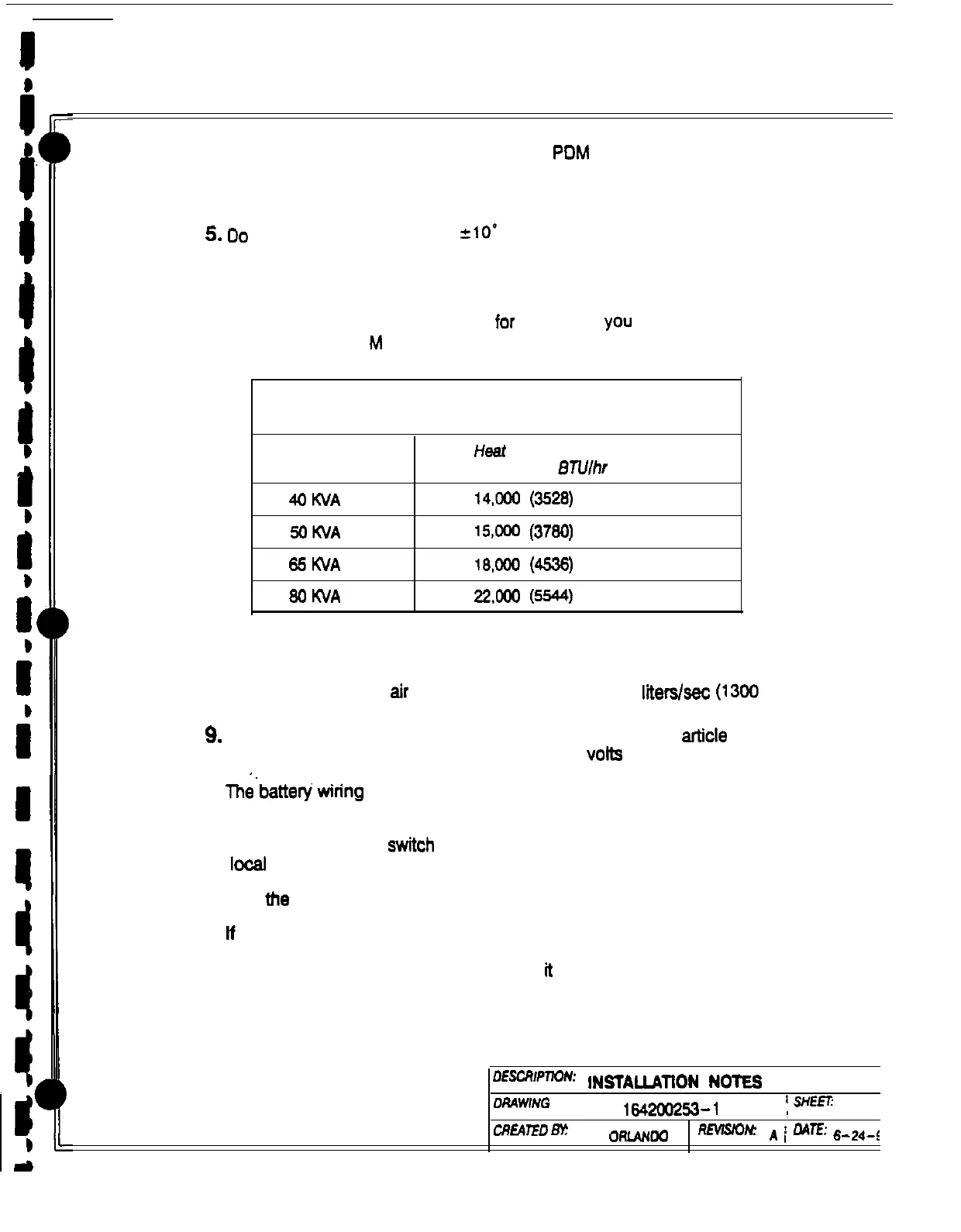
7. If perforated floor tiles are required for ventilation. you should place them in front
of the UPS. Table
M
lists the ventilation requirements for full load operation:
Table M.
Air Conditioning or Ventilation
Requirements During Full Load Operation
Ratings
Heat Rejection
(Kg-cailhr)
BTlJlhr
4oKVA
14,cw
(3528)
5OKVA 15,ooc
(3780)
65KVA
18,ooo
ww
8oWA
2aoo
ww
8.
Recommended minimum clearance over the UPS module is 304.8 mm (12 in.).
Required for cooling
air
exhaust: approximately 814.0 lllers$sec (1300 cfm).
9.
Battery voltage is computed at 2 volts per cell as defined by article 480 of the
NEC. Rated battery current is computed at 1.8 volta per cell.
10.
The’battew wiring used between the battery and the UPS should not allow a
voltage drop of more than 1% of nominal DC voltage at rated battery current
11.
A battery disconnect switch is recommended, and may be required by NEC or
local codes when batteries are remotely located. The battery disconnect switch
may be supplied as an accessory, and should be installed between the battery
and tfte UPS.
12.
If
the conductors used for DC input from the battery cabinet(s) to the UPS are
those provided by the UPS manufacturer, and the UPS and battery cabinet are
manufactured by the same supplier, then
1
is acceptable if they do not meet the
noted minimum conductor sizes.
DEscRIpmN’
INSTALLATtON
NOTES
DRAWtNG
NO:
1642aG?53-1
I=-
2of
CREAlED
Ek!
L
oattim
RMsio~
A
/
nA7.E
S-2&$