13. Use Class
I
wiring methods for control wiring. Install the control wiring in
separate conduit from the power wiring. The wire should be rated at 24 volts. 1
amp minimum.
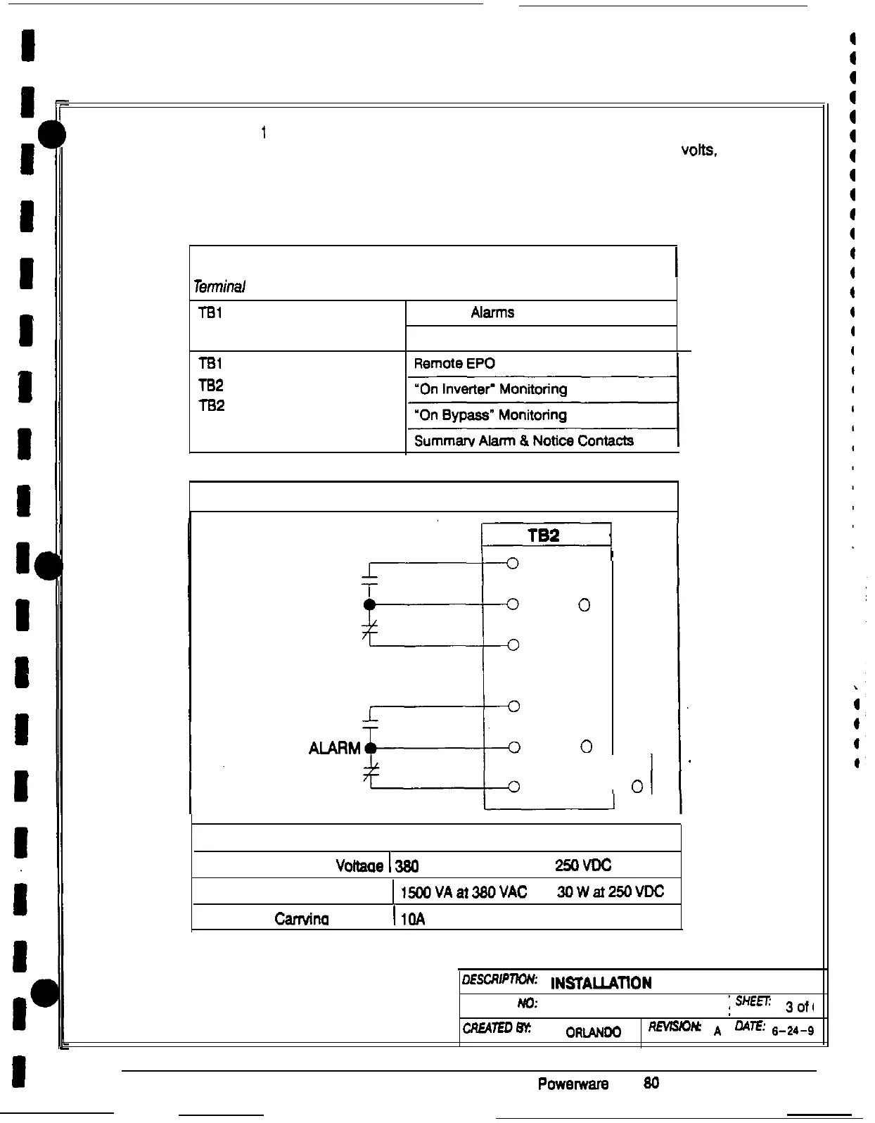
14. Refer to Tables N, 0, and P, and to applicable chapters for information about
installing control wiring for options and accessories.
Table N. Control Wiring Terminations
Teminal
TSl
Description
/
Terminal Block
Terminal Function
Building
Alarms
(optional, up to 3)
Generator Interface
TSl
TB2
TB2
Terminal Block
Table 0. Summary Alarm Relay Contacts
14
0
NOTICE 15
0
13
0
11
0
AJARM 12
0
+---l-4
10
0
I
CONTACT RATING:
Maximum Switched Voiiaae
1
380
VAC
25oVDC
Switching Capacity
EUOVAai38oVAC 3owet25LJvDc
Maximum Carwina Current
I
1OA
A-4
oEsCR’pTKx(:
INSTALlATtON
NOTES
DRAWING No:
164200253-l
;s=
3o+,
cRu\lwBy:
L
ORLANca
RMslo~
A
;
OAlE:
6-24-S
po~ef~are
Plus 80 UPS Installation Manual