1
18.
The output of the UPS is a separately derived source. Output neutral is bonded
to equipment ground through the main bonding jumper. Refer to NEC article
250 and local codes for proper grounding practices.
1%
External overcurrent protection is not provided by this product, but is required
by codes. Refer to Table L on page A-2 for wiring requirements. If an output
lockable disconnect is required, it is to be supplied by others.
20.
When an input transformer is present, the rectifier and bypass inputs may both
be supplied by the same source.
21.
The distribution panel in the PDM has
84
poles.
22.
The PDM cabinet is bottom entry only
23.
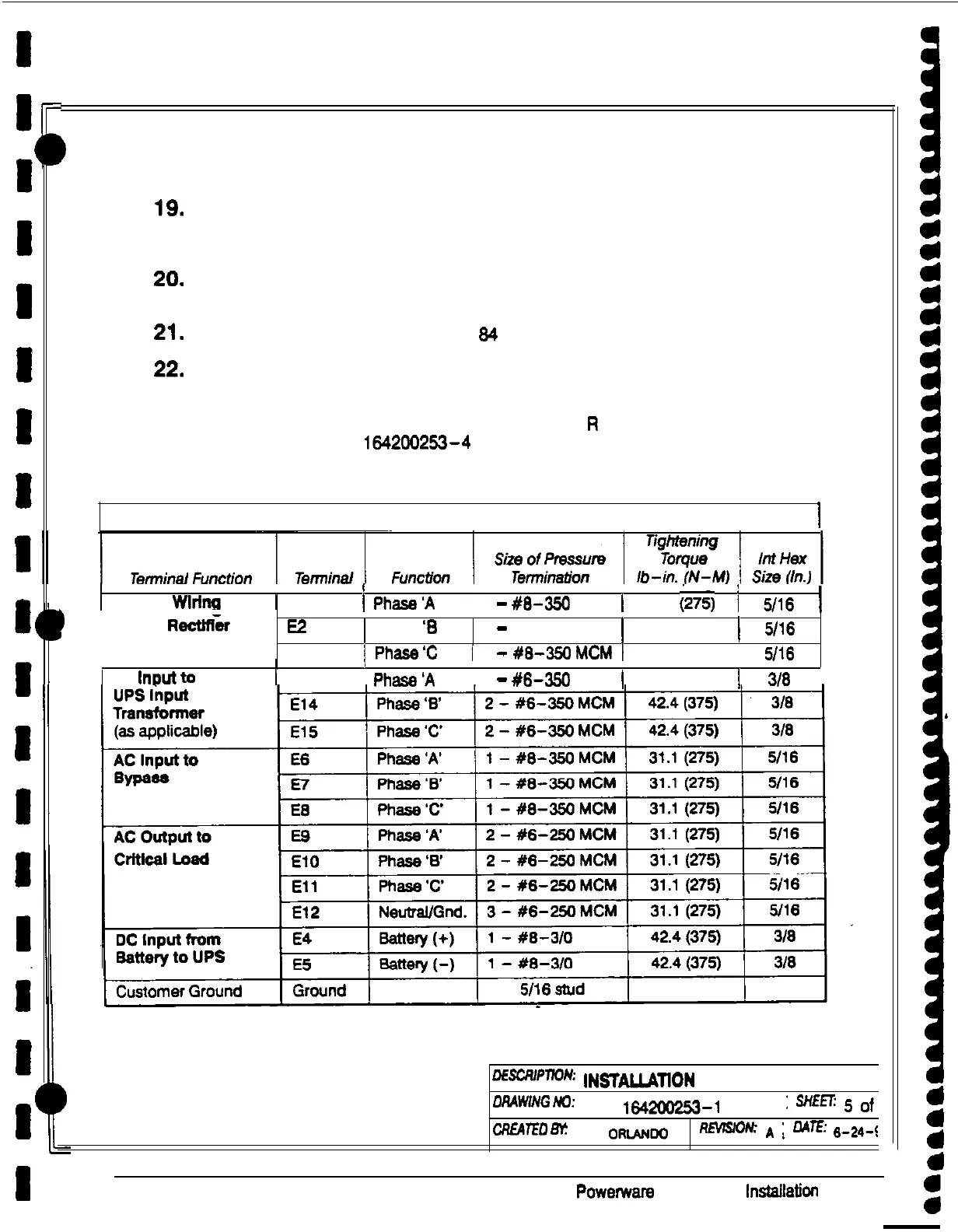
Terminals El through El5 are UL and CSA rated at SO’C. A hex key tool is
required to attach wires to terminals. Refer to Table
R
for power cable
terminations. Drawing 164200253-4 on page A-l 1 shows the location of
these power cable terminals inside the UPS cabinet.
Table R. Power Cable Terminations
I
,
! I
I
Internal
Wlrlng
1 El 1
Phase’A
I
1
-
#6-350
MCM
1
31.1
(275)
i
506
1
1
to
UPS
RH&
E2
Phase
‘6
1
-
#6-350 MCM 1
31.1
(275) 1
5116
Phasa’C
1
-
#6-35OMCM
31.1
506
I
E3 1
1
/
I
1
I
(275) 1
I
AC
lrmut to
1 El3 1
Phase’A
1
2
-
#6-350
MCM
(
42.4 (375)
/
316
DEscRIpnOw
IN!3TALLAllON
NOTES
ORAWiNG
No:
1642aa53-1
:
SHEET:
s
of
CREAlEn m!
L
ORIANDo
VwvlSKW
A
;
A4l.E:
,+*.$q
A-6
Powerware Plus 60 UPS
lnstsilatlon Manual
1