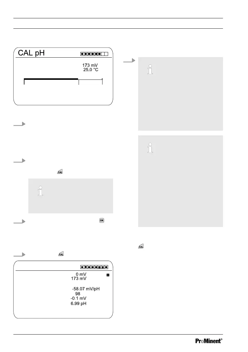
Sensor voltage
Sensor calibration in buffer 2
A1018
Buffer temperature
Stability
acceptable good
Continue with <CAL>
Fig. 41: Display of the sensor stability achieved
12. The range
[acceptable / good / very good]
is dis‐
played.
ð
The black part of the horizontal bar
indicates the determined range.
13. As soon as the black bar appears, the
display changes from
[Please wait!]
to
continue with .
The black bar does not need to
be at [very good].
14.
[Puffer detection]
[Manual]
: Press
and, using the four arrow keys, set the
buffer value for buffer 2 to the value of
the buffer you are using. Press to con‐
firm input of the value.
15. Continue with .
CAL pH
Asymmetry
Buffer 2:
A1019
Zero point
Slope
% Slope
Accept with <CAL>
Buffer 1:
Calibr.param. for 25 °C
Fig. 42: Display of the calibration result
16.
Incorrect calibration
An error message appears if the
result of the calibration lies out‐
side the specified tolerance
limits. In this case the current
calibration is not carried over.
Check the prerequisites for cali‐
bration and eliminate the error.
Then repeat calibration.
Cleaning and care of pH
and ORP sensors
Please note the separate
instructions supplied with the pH
and ORP sensors for cleaning
and care of pH and ORP sen‐
sors.
After cleaning, the sensor must
be conditioned in 3-molar potas‐
sium chloride solution for 60
minutes before it can be reused
for calibration.
Carry over the result of the calibration
into the controller memory by pressing
.
ð
The controller shows the contin‐
uous display again and operates
with the results of the calibration.
Calibration
88