PathMaster® Manual Rev. H 6/03
- 44 -
By using only three points ‘Area’ path segments are calculated in the following manner:
Point 1 defines the start of the pattern. Point 2 defines the direction and length of the pattern. After the
direction of the pattern is determined, the distance from point 1 to point 3 determines the width of the
pattern. The width is divided by the ‘Area Spacing’ (or ‘Path Spacing’) parameter on the Area tool screen.
The resulting value is the number of passes needed to fill the given area.
NOTE: For the above drawings, the X axis is vertical and the Y axis is horizontal.
Area #1
1) Point 1 defines the start.
2) Point 2 is along the X axis, so that is the direction of the path. The length of the path is the distance
over the X axis. Therefore, the width is along the Y axis.
3) Point 3 defines the width. The width is the difference in Y between points 1 and 3. This is divided by
the ‘Area Spacing’ (or ‘Path Spacing’) parameter resulting in the number of paths the machine needs to
run to fill the given area.
Area #2
1) Point 1 defines the start.
2) Point 2 is along the Y axis, so that is the direction of the path. The length of the path is the distance
over the Y axis. Therefore, the width is along the X axis.
3) Point 3 defines the width. The width is the difference in X between points 1 and 3. This is divided by
the ‘Area Spacing’ (or ‘Path Spacing’) parameter resulting in the number of paths the machine needs to
run to fill the given area.
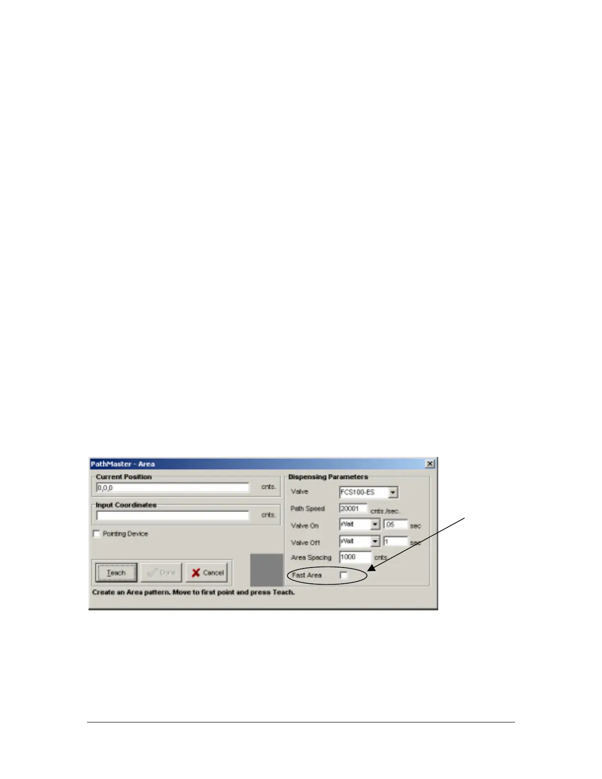
FastArea™
FastArea™ quickens the pace of the standard area by eliminating valve cycling between rows. This feature
can have a dramatic impact on cycle time. To activate the FastArea™ feature; teach a standard area, and
then check the FastArea™ check box.
FastArea™
Check box