! Matrix 832 / 832+ / 424
RINS428-5 Page 125
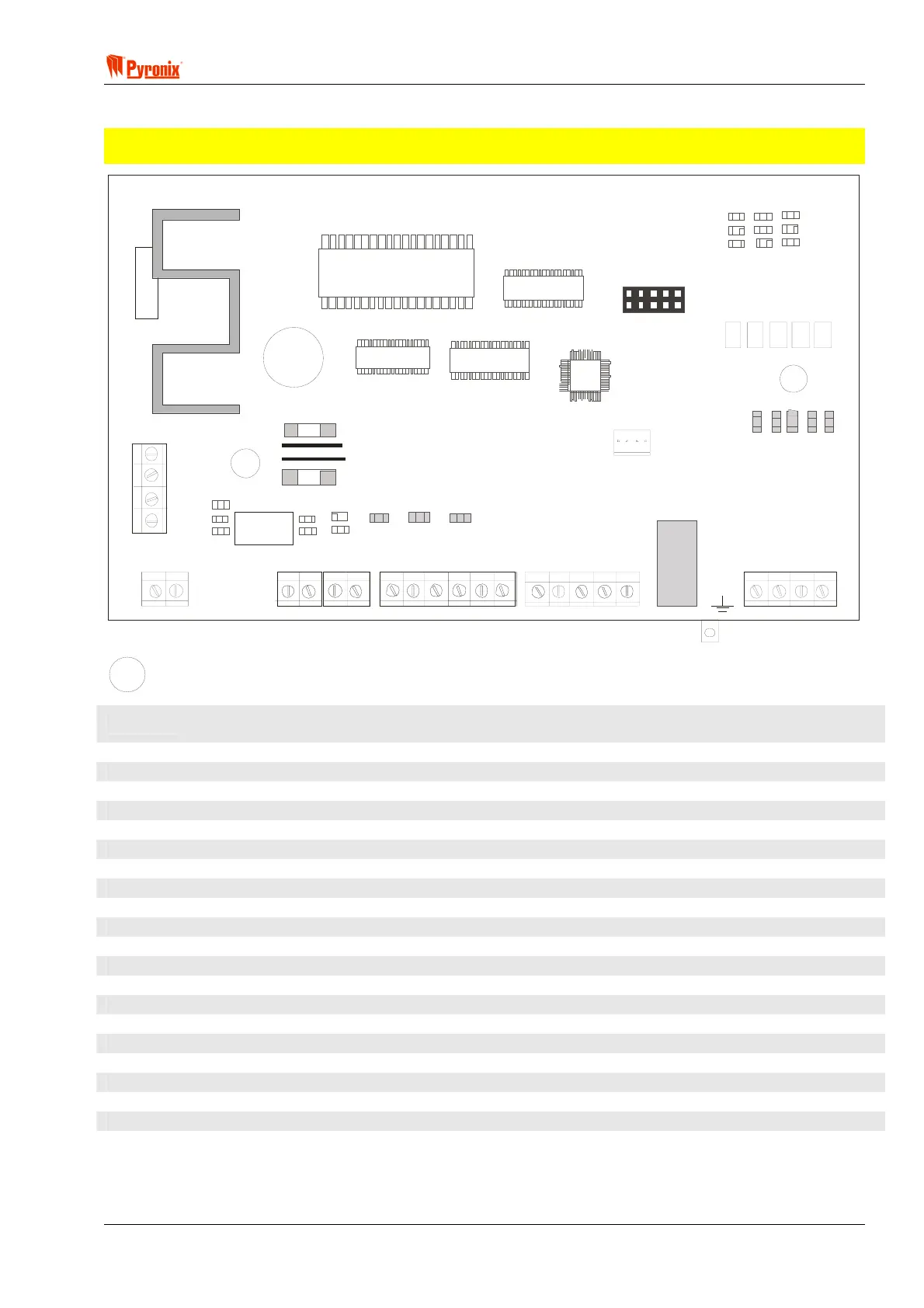
12.4 Matrix 424 PCB
NOTE: The Matrix 424 does not have a Global Tamper (GT) terminal. To create a tamper loop, use the
AUX– terminal and a spare zone programmed as ‘Tamper’.
RS232
NO/
PGM1
PGM2
PGM3
PGM4
+BAT-
17V~
KD
Z1
COM
Z2
+AUX-
Z3
COM
Z4
RING
TIP
R-1
T-1
+BELL-
C
NC
MEANING
17V~
The Matrix panel requires a 17VRMS transformer rated at 44VA for a metal casing, or 21VA for a
plastic casing, or a 17V DC 1.25A supply (protected by a 2A fuse)
+BAT-
Battery connections in order for the Matrix to operate without mains supply
+BELL-
Positive and Negative supply to the bell (protected by a 1A fuse)
NC
Relay programmable output
C
Common
NO/PGM1
Relay programmable output
PGM2
Programmable Output2
PGM3
Programmable Output 3
PGM4
Programmable Output 4
KD
Keypad Data
Z1
Programmable Zone
COM
Common connection for zones (0V)
Z2
Programmable Zone
+AUX-
Auxiliary supply for detectors (protected by a 1A fuse)
Z3
Programmable Zone
COM
Common connection for zones (0V)
Z4
Programmable Zone
RING
Connection to Analogue PSTN telephone line
TIP
Telephone direct connection
R-1
Series connection to telephone line
T-1
To be connected to remaining telephone line equipment within the installation

 Loading...