! Matrix 832 / 832+ / 424
RINS428-5 Page 155
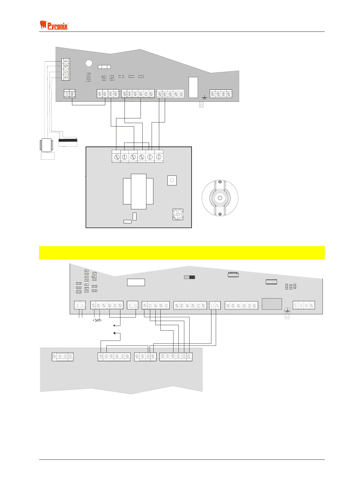
12.12.8 Twin Alert Connection to Matrix 424
+
-
B
AT
+BELL-
Bell Fuse 1Amp
NO/
PGM1
PGM2
PGM3
PGM4
17V AC
Output
+BAT-
KD Z1
COM
COM
Z2 +AUX- Z3 Z4
RING
TIP
R-1
T-1
17V~
TWIN ALERT
T
T
BA
SPK
AUX-
AUX+
IMPORTANT
Twin Alert must be connected to Matrix panel
as illustrated. PGM3 must be programmed as
Twin Alert.
In this illustration NO/PGM1 should be programmed as
‘External Bell’. The tamper connection must be connected
to a spare zone programmed as ‘Tamper’ - in this case Z1
See section 8.6
C
NC
12.12.9 Vocaliser Connection to Matrix 832
NOTE: Terminal Connections to Matrix 424 are the same as to a Matrix 832, except that the tamper is
connected to a zone programmed as ‘Tamper’.
NVM Reset
Relay
17V~ +BAT- B+ B- BT GT NC C
NO1/
PG M1
PG M2
PG M3
PG M4
KD Z1 Z2 Z3 Z4
COM
COM
+AUX- Z5 Z6 Z7 Z8
COM
COM
RING
TIP
R-1
T-1
To Tamper Loop
IMPORTANT
See Vocaliser User guide for complete
Vocaliser programming options.
In this instance programmable
outputs are programmed as follows
PGM1 = “External Bell”
PGM2 = “Follow PA”
PGM3 = “Follow Fire”
PGM4 = C+ (if Abort function is required)
1234
A
B
TT
F
L
T
A
C
K
1
2
V
0
V
+
B
A
T
-
S
P
K
M
-
M
+
A
1
B
1
M
I
C
17AC
Vocaliser Connections
with 4 programmable outputs